Vacuum valve

a vacuum valve and valve body technology, applied in the direction of valve arrangements, lift valves, check valves, etc., can solve the problems of inability to complete the closing (i.e. sealing) of the valve, the use of sealing rings with relatively complicated shapes, and the disadvantages of shear stress acting on the seal, etc., to achieve small nominal widths and simple manners

Active Publication Date: 2006-03-14
VAT HLDG AG
View PDF12 Cites 50 Cited by
  • Summary
  • Abstract
  • Description
  • Claims
  • Application Information

AI Technical Summary

Benefits of technology

[0012]An important object of the invention is to provide a vacuum valve which is constructed in a simple manner. Another object of the invention is to provide a vacuum valve in which only a straight-line displacement of the valve plate is required. Another object of the invention is to provide a vacuum valve which can be completely closed without any differential pressure being applied. Another object of the invention is to provide a vacuum valve in which the sealing ring can be exchanged in a simple manner and wherein the valve is suitable for small nominal widths as well as for large nominal widths.
[0014]The invention is based on the insight that a wedge gate valve can advantageously be constructed as a vacuum valve by providing at least one sliding-spacing part which forms a sliding bearing for the valve plate relative to the valve housing when closing the valve along a final distance and which maintains the valve plate at a distance from the valve housing in the closed position of the valve plate and therefore limits the pressing of the sealing ring. Adequately low wear on the sealing ring and a sufficiently low level of particle generation when closing the valve are achieved in this way for many applications—excluding those in which the vacuum valve is opened and closed very frequently. In this regard, the final section of the closing movement in which the at least one sliding-spacing part slides at the valve housing can vary in length depending on the elasticity of the structural component parts, particularly the elasticity of the at least one sliding-spacing part and valve housing, and depending on the deviation of the valve plate from its central position.
[0017]A valve according to the invention can be constructed in a simple and therefore economical manner overall. Simple maintenance is also possible. In a preferred embodiment form of the invention, there are at least two sliding-spacing parts which are spaced apart in circumferential direction of the sealing ring and sealing surface. These sliding-spacing parts each have a length that is substantially shorter than the circumferential length of the sealing ring. In this connection, it is advantageous when all of these sliding-spacing parts lie at a greater distance along their entire extension from an axis extending parallel to the displacement direction and running through the center of the valve plate or valve body and the valve opening than the sealing ring at its farthest point from this axis. Accordingly, no abrasion marks running along the sealing surface or sealing ring (when the valve plate deviates from its centered position) can occur as a result of the sliding-spacing parts when opening and closing the valve.
[0018]In an advantageous constructional variant, the sliding-spacing parts lock into recesses in the valve plate or valve housing by means of a locking connection and can accordingly also be exchanged in a simple manner.

Problems solved by technology

A shear stress of this kind acting on the seal is generally considered very disadvantageous with respect to the life of the seal.
This slide valve is disadvantageous in that sealing rings with relatively complicated shapes must be used; these sealing rings cannot be formed as O-rings inserted into a groove for larger nominal widths but must be vulcanized to the valve plate.
Therefore, the entire valve plate must be exchanged when the sealing ring is damaged.
However, a complete closing (i.e., sealing) of the valve is not possible without a differential force of this kind.

Method used


Image

  • Vacuum valve
  • Vacuum valve
  • Vacuum valve

Examples


Embodiment Construction

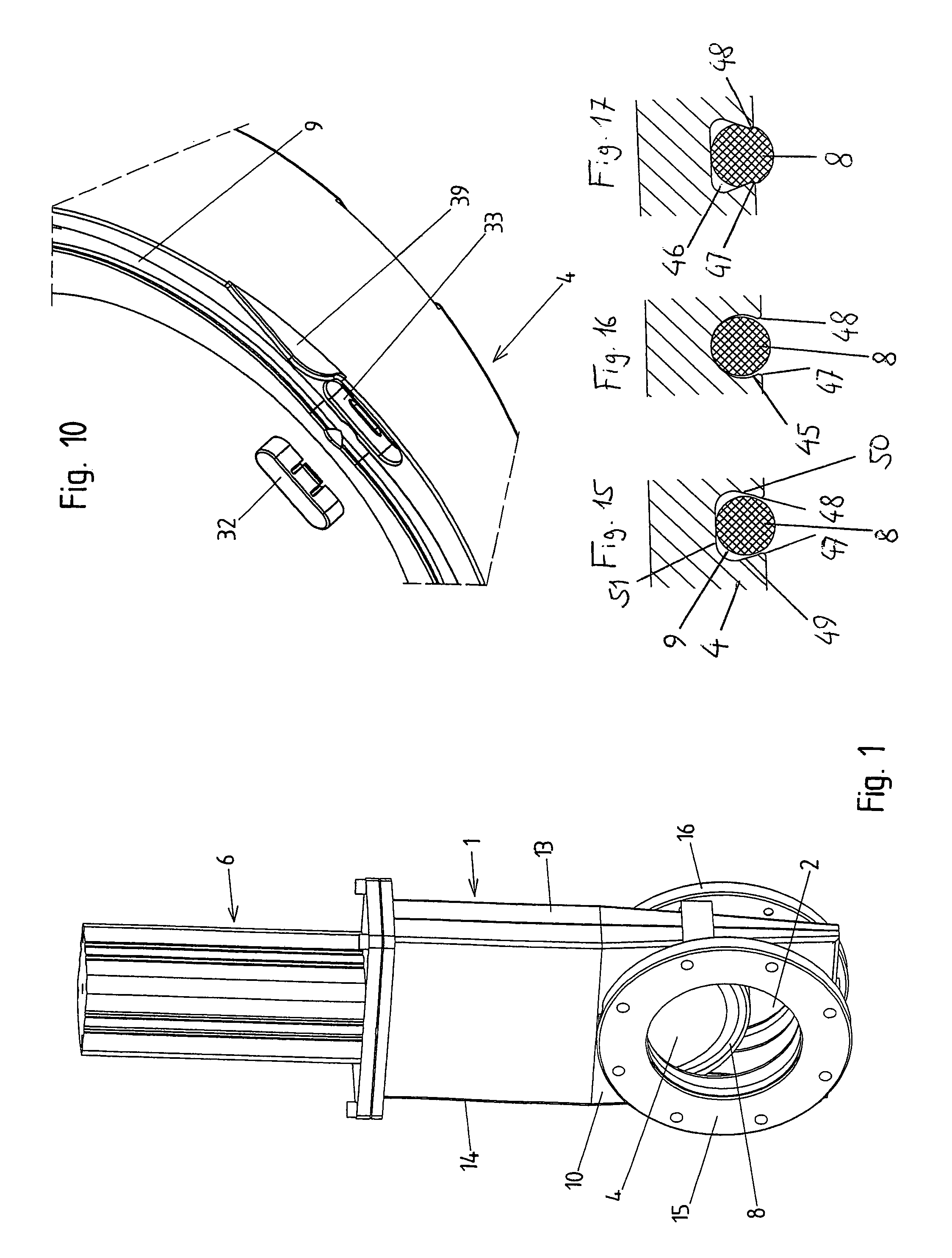
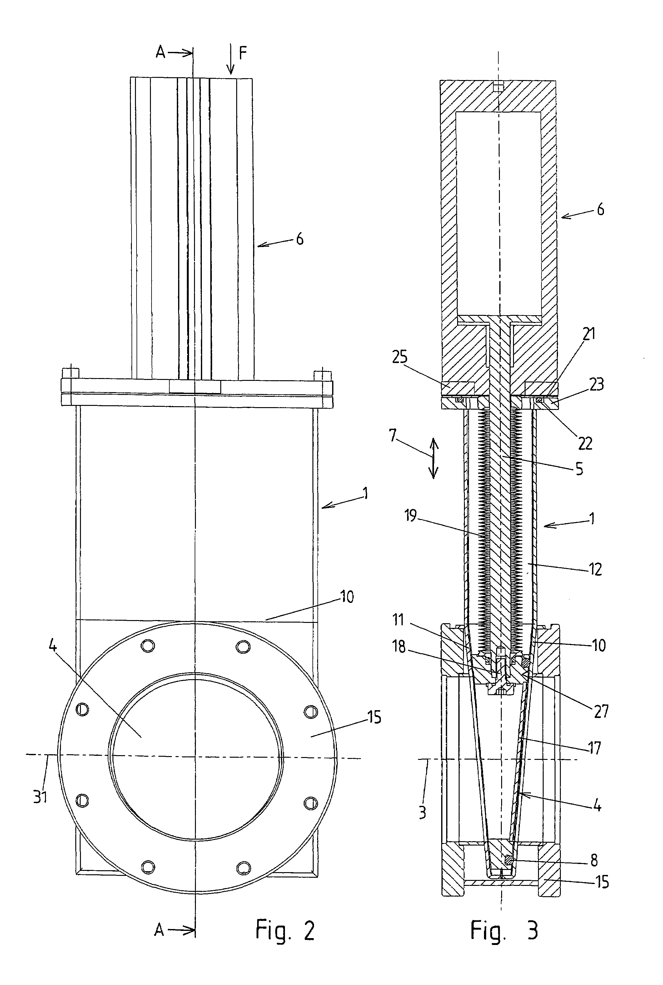
[0036]An embodiment example of a vacuum valve according to the invention is shown in FIGS. 1 to 13. The vacuum valve comprises a valve housing 1 with a valve opening 2 having a longitudinal axis 3. A valve plate 4 is mounted so as to be displaceable in a straight line (i.e., linearly) in the valve housing 1. To this end, the valve plate is arranged at a valve rod 5 which is displaceable in a straight line by an actuating device 6, shown only schematically, in direction of its longitudinal axis. The actuating device (actuator) 6 can be formed, for example, by a pneumatic piston-cylinder unit. Actuating devices having electric motors, for example, could also be used. Suitable actuating devices for axial displacement of the valve rod 5 are known and need not be described in detail within the scope of this application.

[0037]A movement of the valve rod 5 and of the valve plate 4 need only be carried out by the actuating device in one straight-line displacement direction 7. This displacem...


PUM


Abstract

A vacuum valve comprises a valve housing with a valve opening having a longitudinal axis and a valve seat, a valve plate which is displaceable in a straight line in a displacement direction between an open position in which it releases the valve opening and a closed position in which its contacts the valve seat of the valve housing and closes and seals the valve opening, this valve plate being arranged on at least one valve rod which is displaceable axial to the displacement of the valve plate, a flexible sealing ring which is arranged at a front side of the valve plate or at the valve seat of the valve housing, a sealing surface which is arranged at the valve seat of the valve housing or at the front side of the valve plate and which is contacted by the sealing ring in the closed position of the valve plate, wherein the sealing surface and the sealing ring are arranged in parallel planes which are inclined relative to the displacement direction of the valve plate around an axis extending at right angles to the displacement direction and at right angles to the longitudinal axis of the valve opening, and at least one sliding-spacing part which is arranged at the front side of the valve plate next to the sealing ring or sealing surface or at the valve seat next to the sealing surface or sealing ring and which forms a sliding bearing for the valve plate relative to the valve housing when closing the valve along a final section of the displacement path of the valve plate until the closed position of the valve plate is reached and which keeps the valve plate at a distance from the valve housing in the closed position of the valve plate and accordingly limits the pressing of the sealing ring.

Description

BACKGROUND OF THE INVENTION[0001]a) Field of the Invention[0002]The invention is directed to a vacuum valve comprising a valve housing with a valve opening having a longitudinal axis and a valve seat, a valve plate which is displaceable in a straight line in a displacement direction between an open position in which it releases the valve opening and a closed position in which its contacts the valve seat of the valve housing and closes and seals the valve opening, this valve plate being arranged on at least one valve rod which is displaceable axial to the displacement of the valve plate, a flexible sealing ring which is arranged at a front side of the valve plate or at the valve seat of the valve housing, a sealing surface which is arranged at the valve seat of the valve housing or at the front side of the valve plate and which is contacted by the sealing ring in the closed position of the valve plate, wherein the sealing surface and the sealing ring are arranged in parallel planes w...

Claims


Application Information

Patent Timeline
Patent Type & Authority Patents(United States)
IPC IPC(8): F16K3/00
CPCF16K3/0218F16K51/02F16K3/14F16K3/0227F16K3/02
Inventor EHRNE, FLORIANBACHMANN, CHRISTOFGEISER, FRIEDRICH
Owner VAT HLDG AG
Why Eureka
Try Eureka