Variable magnetic resistance unit for an exercise device

a technology of magnetic resistance unit and exercise device, which is applied in the field of magnetic resistance unit, can solve the problems of increasing the difficulty of rotating roller and bicycle wheel

Inactive Publication Date: 2006-03-14
SARIS EQUIP LLC
View PDF63 Cites 130 Cited by
  • Summary
  • Abstract
  • Description
  • Claims
  • Application Information

AI Technical Summary

Benefits of technology

[0007]It is an object of the present invention to provide a magnetic resistance unit for a bicycle ...

Problems solved by technology

As the diameter of the path defined by the magnets increases, the distance of the eddy currents from the axis of rotation increases, whic...

Method used


Image

  • Variable magnetic resistance unit for an exercise device
  • Variable magnetic resistance unit for an exercise device
  • Variable magnetic resistance unit for an exercise device

Examples


Embodiment Construction

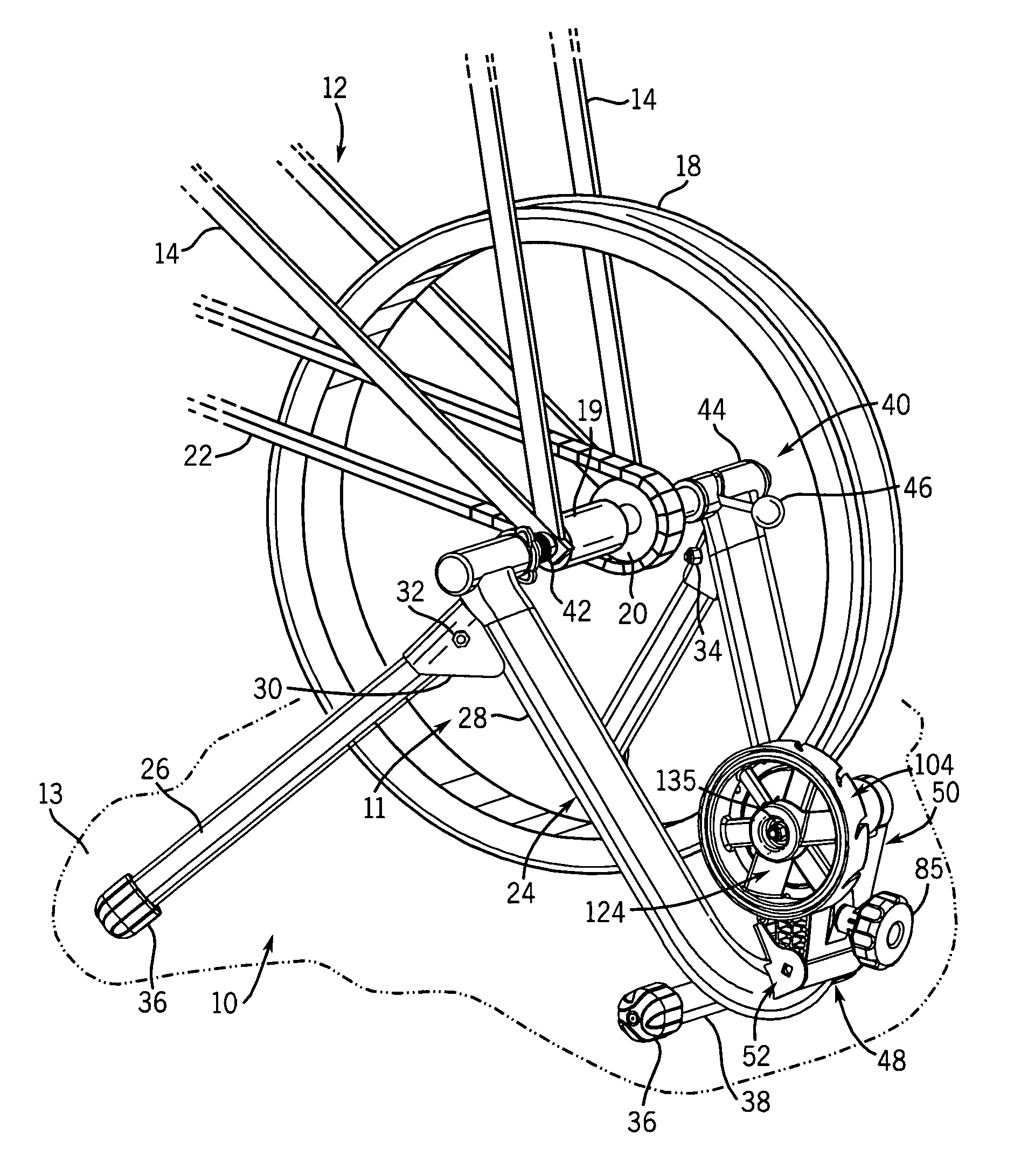
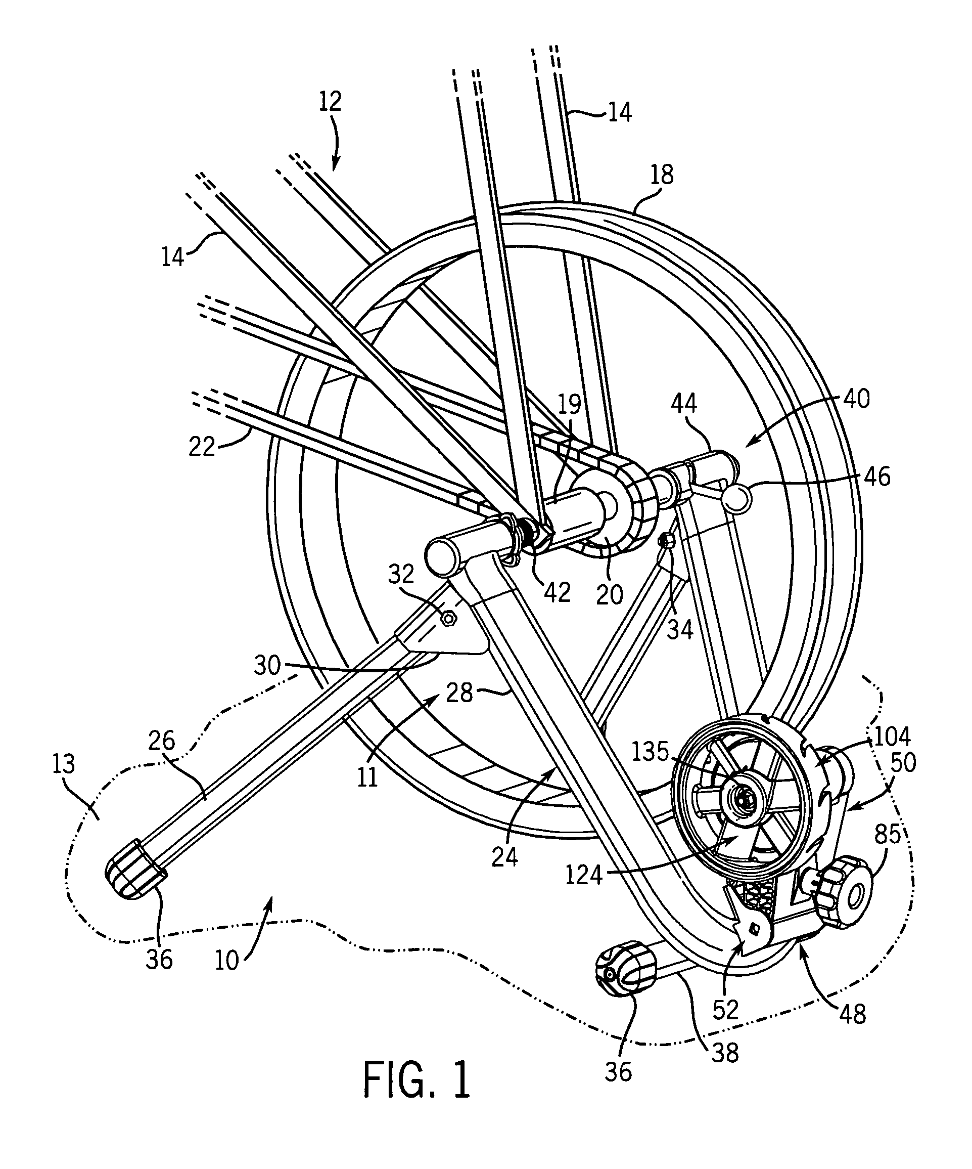
[0024]With reference now to the drawing figures in which like reference numerals designate like parts throughout the disclosure, a bicycle training device is indicated generally at 10 in FIG. 1. The device 10 includes a frame 11 that is adapted to releasably support a bicycle 12. The frame 11 rests on a horizontal surface 13 and can be a frame similar to that which is incorporated in any conventional bicycle trainer and which is capable of releasably engaging either the frame or a rear wheel of a bicycle, such as is incorporated into trainers manufactured by the Cycle-Ops division of Graber Products, Inc. of Madison, Wis. Bicycle 12 includes downwardly extending frame members or stays 14 that support the hub 19 of a wheel 18 associated with bicycle 12. Hub 19 carries a sprocket 20 driven by a chain 22 in response to a conventional pedal and crank assembly associated with bicycle 10, in a manner as is known

[0025]The frame 11 has a pair of generally forwardly extending legs 26 attache...


PUM


Abstract

An automatically adjusting magnetic resistance unit for an exercise device such as a bicycle trainer, in which the degree of resistance is automatically and non-linearly adjusted in relation to the rotational speed of a rotating member caused by the input of a user. The rotating member may be in the form of a flywheel having a number of supports extending between a hub and a rim. The supports define longitudinal grooves which slidably retain magnets that are biased inwardly toward the hub by biasing members. An electrically conductive member is located adjacent the flywheel. As the flywheel rotates in response to rotation of the bicycle wheel, the magnets interact with the conductive member to establish eddy currents that provide resistance to the rotation of the flywheel. The speed of rotation of the flywheel increases as the speed of rotation of the bicycle wheel increases, and centrifugal forces act on the magnets to cause the magnets to slide outwardly along the grooves in opposition to the bias of the biasing members. The outward movement of the magnets causes outward movement of the eddy current forces, to increase the resistance provided to rotation of the flywheel and the bicycle wheel. The variable resistance due to the increased or decreased rotational speed of the flywheel is smooth, based on the constant interaction of the counteracting forces of the biasing members and the centrifugal forces acting on the magnets.

Description

FIELD OF THE INVENTION[0001]The present invention relates to exercise devices, and more specifically to a magnetic resistance unit adapted to be used in connection with an exercise device such as a bicycle trainer.BACKGROUND OF THE INVENTION[0002]A number of resistance-type bicycle training devices have been developed that allow a person to stationarily train on a bicycle. Such bicycle training devices are commonly used indoors when it is not possible to ride the bicycle out of doors. Such bicycle training devices normally include a collapsible frame positionable on a floor and releasably attachable to the rear wheel of the bicycle. The frame supports a resistance unit which engages the rear wheel of the bicycle supported by the frame, to provide resistance to the rotation of the wheel. Therefore, as the person moves the pedals and, consequently, the rear wheel of the bicycle, the rotation of the wheel is opposed by the resistance provided by the resistance unit.[0003]The resistance...

Claims


Application Information

Patent Timeline
IPC IPC(8): A63B69/16A63B21/005A63B21/22
CPCA63B21/0051A63B69/16A63B21/225A63B2069/165
Inventor KOLDA, CLINT D.PIN, CHANG SHINHUA, ZHU ZHAO
Owner SARIS EQUIP LLC
Why Eureka
Try Eureka