Display device having light blocking layer, and electric device

a technology of light blocking layer and display device, which is applied in the direction of discharge tube luminescnet screen, discharge tube/lamp details, electric discharge lamps, etc., can solve the problems of color bleeding and the risk of a decrease in the contrast ratio of the display apparatus, and achieve the effect of enhancing the adhesion between the first bank layer and the second bank layer

Inactive Publication Date: 2006-03-14
SEIKO EPSON CORP
View PDF35 Cites 98 Cited by
  • Summary
  • Abstract
  • Description
  • Claims
  • Application Information

AI Technical Summary

Benefits of technology

[0045]In addition, in the case of providing a light blocking layer between a first bank layer and a second bank layer, the adhesion between the first bank layer and second bank layer can be enhanced.

Problems solved by technology

However, in this display apparatus of the prior art, since colored light emitted from luminescent layers expands to not only the observer's side, but also around the periphery of the luminescent layers (regions at which luminescent layers are not formed), colored light emitted from adjacent luminescent layers on both sides of these non-formed regions end up mixing, resulting in the occurrence of color bleeding, while also leading to the risk of a decrease in the contrast ratio of the display apparatus.

Method used


Image

  • Display device having light blocking layer, and electric device
  • Display device having light blocking layer, and electric device
  • Display device having light blocking layer, and electric device

Examples


first embodiment

[0078][First Embodiment]

[0079]The following provides an explanation of a first embodiment of the present invention with reference to the drawings.

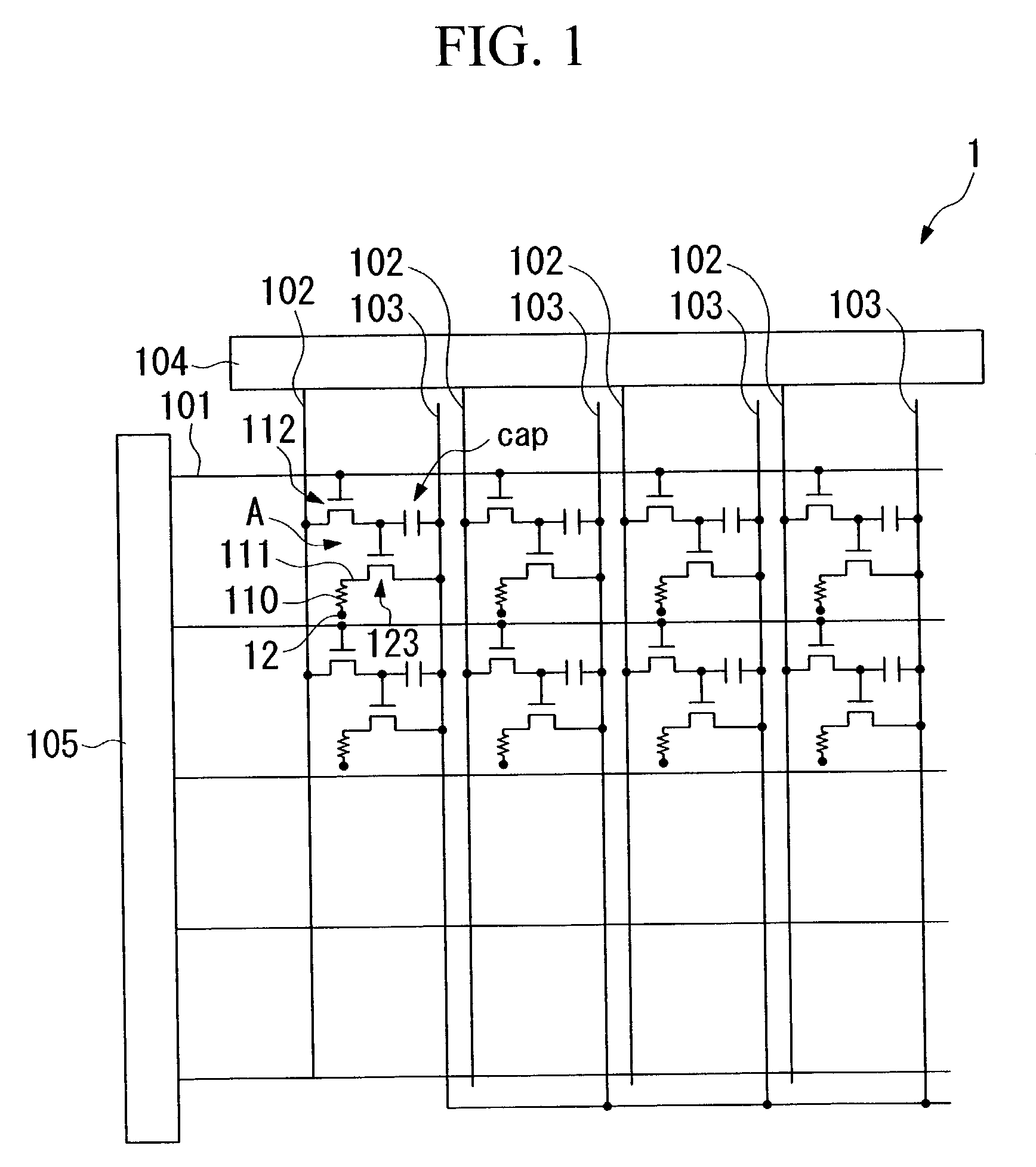
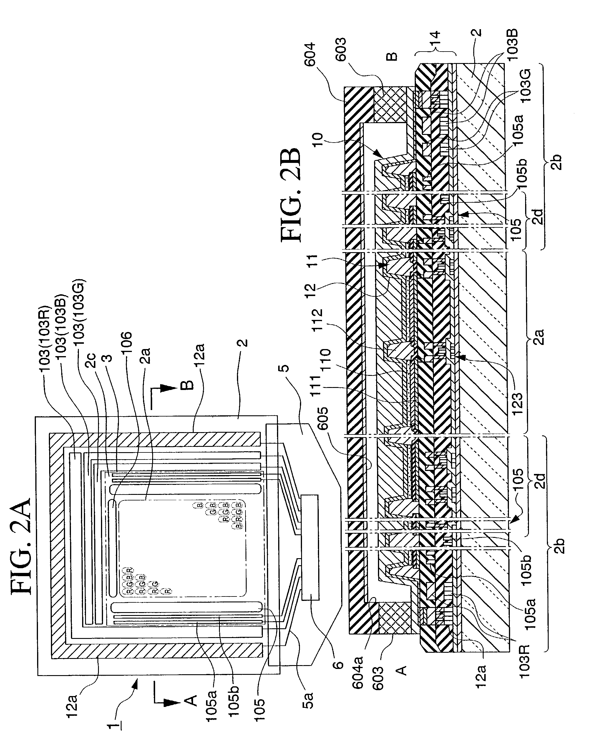
[0080]FIG. 1 shows an overhead schematic drawing of the wiring structure of a display apparatus of the present embodiment of the invention, while FIG. 2 shows an overhead schematic drawing and cross-sectional schematic drawing of a display apparatus of the present embodiment of the invention.

[0081]As shown in FIG. 1, a display apparatus 1 of the present embodiment of the invention is provided with pixel regions A having a constitution in which a plurality of scanning lines 101, a plurality of signal lines 102 extending in a direction that intersects scanning lines 101, and a plurality of power lines 103 extending in a direction in parallel with signal lines 102, are respectively wired, and which are located near each intersection of scanning lines 101 and signal lines 102.

[0082]Data side drive circuit 104 provided with a shift register, le...

second embodiment

[0265][Second Embodiment]

[0266]Next, an explanation is provided of a second embodiment of the present invention with reference to the drawings.

[0267]FIG. 21 is a cross-sectional view showing the essential portion of a display apparatus of the second embodiment.

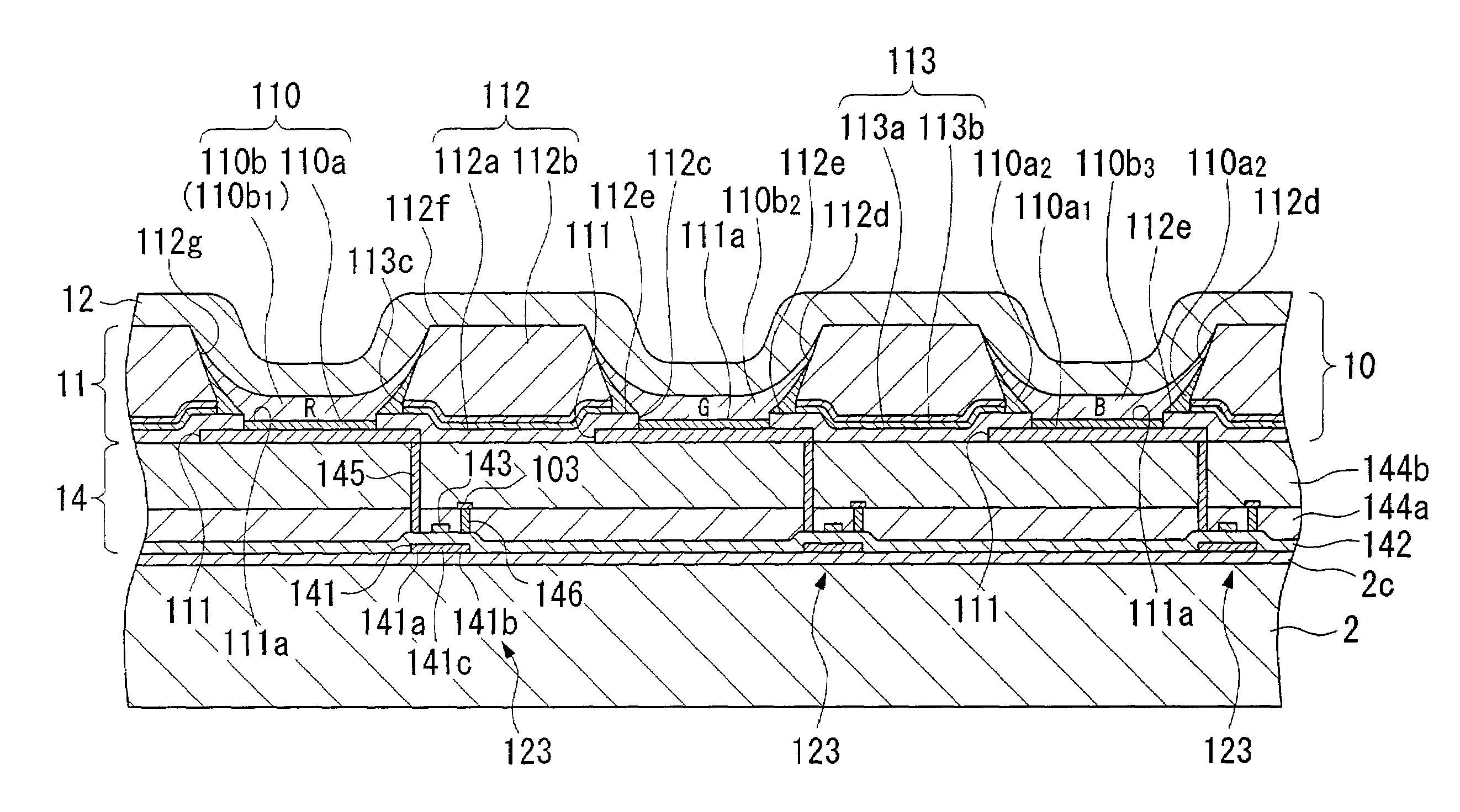
[0268]As shown in FIG. 21, the display apparatus of the present embodiment is composed by sequentially laminating a circuit element section 14 in which TFT and other circuits are formed, luminescent element section 211 in which a luminescent layer is formed, and cathode 12 on a substrate 2.

[0269]In the display apparatus as claimed in the present embodiment, similar to the case of the first embodiment, light emitted from functional layer 110 on the side of substrate 2 is emitted towards the lower side (observer side) of substrate 2 after passing through circuit element section 14 and substrate 2, while light emitted from functional layer 110 towards the opposite side of substrate 2 is reflected by cathode 12 and emitted towards...

third embodiment

[0282][Third Embodiment]

[0283]The following provides an explanation of a third embodiment of the present invention with reference to the drawings.

[0284]FIG. 22 is a cross-sectional view showing the essential portion of a display apparatus of the third embodiment.

[0285]As shown in FIG. 22, the display apparatus of the present embodiment is composed by sequentially laminating a circuit element section 14 in which TFT and other circuits are formed, luminescent element section 311 in which a luminescent layer is formed, and cathode 12 on a substrate 2.

[0286]In the display apparatus as claimed in the present embodiment, similar to the cases of the first and second embodiments, light emitted from functional layer 110 on the side of substrate 2 is emitted towards the lower side (observer side) of substrate 2 after passing through circuit element section 14 and substrate 2, while light emitted from functional layer 110 towards the opposite side of substrate 2 is reflected by cathode 12 and ...


PUM


Abstract

A display apparatus is provided that prevents shortening of the life of the luminescent elements and has a superior contrast ratio. The display apparatus is composed by forming a plurality of luminescent elements on a substrate and providing bank sections between each of the luminescent elements. The bank sections are formed from a first bank layer located on the side of the substrate and a second bank layer formed on the first bank layer. A light blocking layer is then provided between the first bank layer and the second bank layer.

Description

BACKGROUND OF THE INVENTION[0001]1. Field of the Invention[0002]The present invention relates to a display apparatus and electric device.[0003]2. Background Art[0004]As a result of the growing use of organic fluorescent materials and other luminescent materials as ink, and the proliferation of ink jet methods that discharge said ink (composition) onto a base material in recent years, color display apparatuses employing a structure in which a luminescent layer composed of said luminescent material is interposed between an anode and cathode, and particularly organic electroluminescence (EL) display apparatuses using an organic luminescent material for the luminescent material, are being developed by employing methods for patterning luminescent materials (refer to Patent Document 1 (Japanese Patent Unexamined Application, First Publication No. 10-12377)).[0005]Therefore, the following provides an explanation of a display apparatus of the prior art (organic EL display apparatus) with re...

Claims


Application Information

Patent Timeline
Patent Type & Authority Patents(United States)
IPC IPC(8): H05B33/10H05B33/22H01L27/32H01L51/50H01L51/52H05B33/12
CPCH01L51/5284H01L27/3246H01L27/3211H10K59/35H10K59/122H10K50/865H05B33/22
Inventor SEKI, SHUNICHI
Owner SEIKO EPSON CORP
Why Eureka
Try Eureka