Controller for a power factor corrector and method of regulating the power factor corrector

a technology of power factor corrector and controller, which is applied in the field of power electronics, can solve the problems of contributing to electromagnetic interference noise, rectifier bridge subject to dissipative losses, and conventional boost converters cannot directly process the ac power available from the ac lin

Inactive Publication Date: 2006-03-14
LINEAGE POWER
View PDF6 Cites 92 Cited by
  • Summary
  • Abstract
  • Description
  • Claims
  • Application Information

AI Technical Summary

Benefits of technology

[0012]The controller includes a sensing circuit that detects a sense current that is representative of the input current to the power factor corrector. The controller also includes a frequency modulation circuit, coupled to the sensing circuit, that provides a signal that causes at least one of: (a) an increase of the switching frequency of the power switch when the input current increases, and (b) a decrease of th

Problems solved by technology

The conventional boost converter, however, cannot directly process the AC power available from the AC line.
The rectifier bridge is subject to dissipative losses, particularly at low AC line voltages (e.g., 85 to 100 VAC).
Further, the rectifier bridge may contribute to electromagnetic interference noise generated by the power factor corrector.
Analogous to other types of power supplies, the power factor corrector is subject to further inefficiencies that impair its overall performance.
More specifically, the power switch and boost diode may be subject to conduction losses that reduce the efficiency of the power factor corrector.
Additionally, the power switch (e.g., field-effect transistor) is subject to switching losses that occur, in part, when a charge built up in a parasitic capacitance of the power switch is dissipated when the power switch is transitioned to a conducting state.
Furthermore, the boost diode may also be subject to a reverse recovery phenomenon, when the power switch is conducting, that induces a substantial current spike through both the power switch and the boost

Method used


Image

  • Controller for a power factor corrector and method of regulating the power factor corrector
  • Controller for a power factor corrector and method of regulating the power factor corrector
  • Controller for a power factor corrector and method of regulating the power factor corrector

Examples


Embodiment Construction

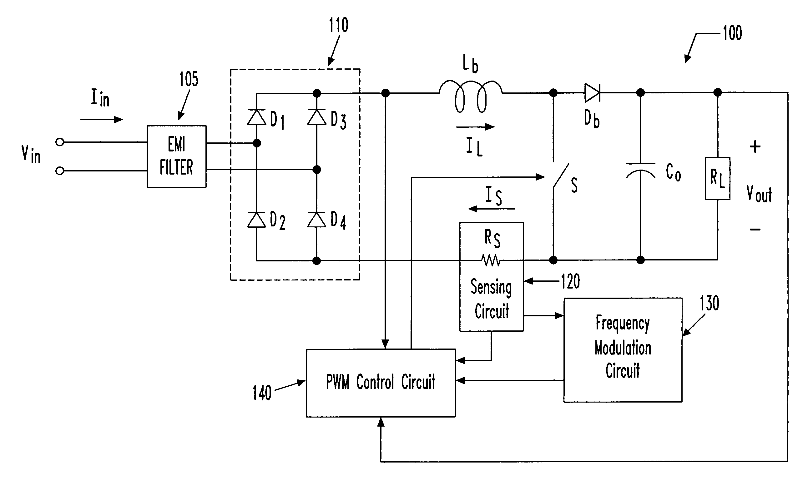
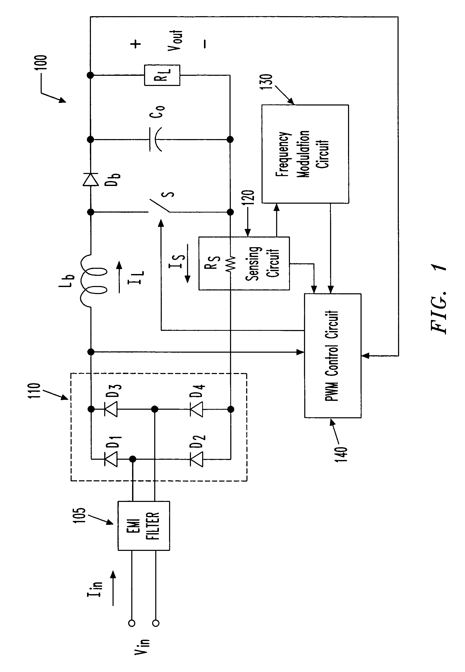
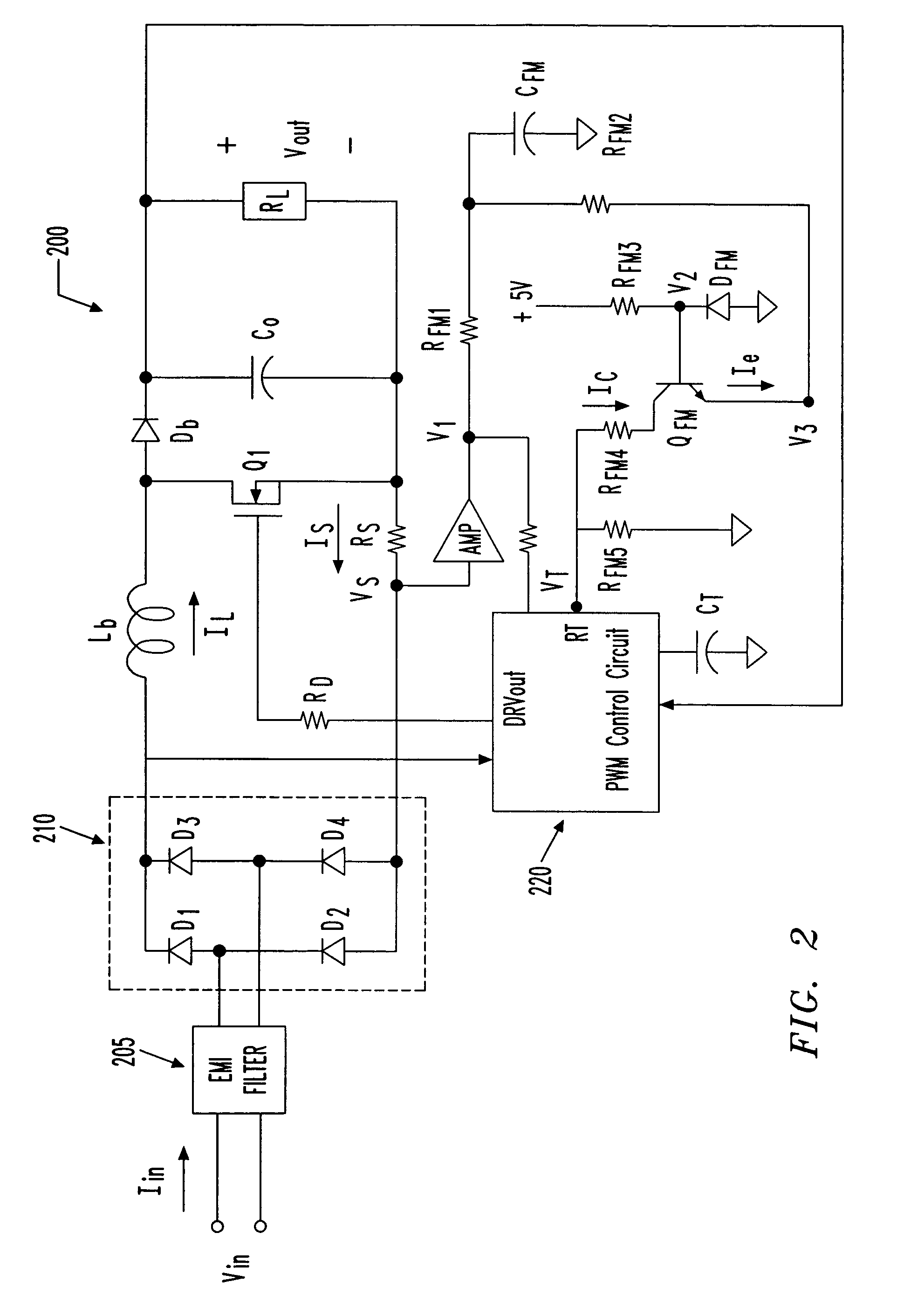
[0018]Referring initially to FIG. 1, illustrated is a schematic diagram of an embodiment of a current-controlled frequency-modulated power factor corrector (also referred to as a power factor corrector) 100 constructed according to the principles of the present invention. The power factor corrector 100 has an input couplable to an AC source (not shown) having an input voltage Vin and supplying an input current Iin. The power factor corrector 100 provides an output voltage Vout at an output thereof. The power factor corrector 100 includes an electromagnetic interference (also referred to as “EMI”) filter 105 and a rectifier 110 having first, second, third and fourth diodes D1, D2, D3, D4.

[0019]The power factor corrector 100 employs a boost converter topology having a boost inductor Lb (with a boost inductor current IL passing therethrough), a power switch S, a boost diode Db and an output capacitor Co. A characteristic of the boost converter topology is that the output voltage Vout i...


PUM


Abstract

A controller for use with a current-controlled frequency-modulated power factor corrector having a power switch therein, and a method of regulating the same. In one embodiment, the controller includes a sensing circuit configured to detect a sense current that is representative of an input current to the power factor corrector. The controller also includes a frequency modulation circuit, coupled to the sensing circuit, configured to provide a signal that causes at least one of: (a) an increase of a switching frequency of the power switch when the input current increases, and (b) a decrease of the switching frequency of the power switch when the input current decreases.

Description

TECHNICAL FIELD OF THE INVENTION[0001]The present invention is directed, in general, to power electronics and, more specifically, to a controller for a power factor corrector and a method of regulating the same.BACKGROUND OF THE INVENTION[0002]A power converter is a power processing circuit that converts an input voltage or current source waveform into a specified output voltage or current waveform. A switched-mode power converter is a frequently employed power converter that converts an input voltage waveform into a specified output voltage waveform. A boost converter is one example of a switched-mode power converter that is typically employed in off-line applications wherein power factor correction at the input and a stable, regulated voltage at the output are desired.[0003]A non-isolated boost converter may form a portion of a power factor corrector and generally includes a boost inductor and a power switch coupled to the boost inductor. The boost converter further includes a boo...

Claims


Application Information

Patent Timeline
IPC IPC(8): G05F1/40H02M1/12
CPCH02M1/42Y02B70/12Y02B70/10
Inventor YE, ZHONG
Owner LINEAGE POWER
Why Eureka
Try Eureka