Battery tester upgrade using software key

a software key and battery tester technology, applied in the field of storage batteries, can solve the problems of adding significant overhead to the operation of the vendor, affecting the user's experience,

Active Publication Date: 2006-03-14
MIDTRONICS
View PDF304 Cites 104 Cited by
  • Summary
  • Abstract
  • Description
  • Claims
  • Application Information

AI Technical Summary

Problems solved by technology

This series of transactions creates delays that may frustrate the user, while adding significant overhead to the vendor's operations.

Method used


Image

  • Battery tester upgrade using software key
  • Battery tester upgrade using software key
  • Battery tester upgrade using software key

Examples


Embodiment Construction

[0010]Embodiments of the present invention, described below, all relate to a battery testing system which includes locked battery testing instructions that can be executed upon receipt of a software unlocking key that corresponds to a predetermined software unlocking key.

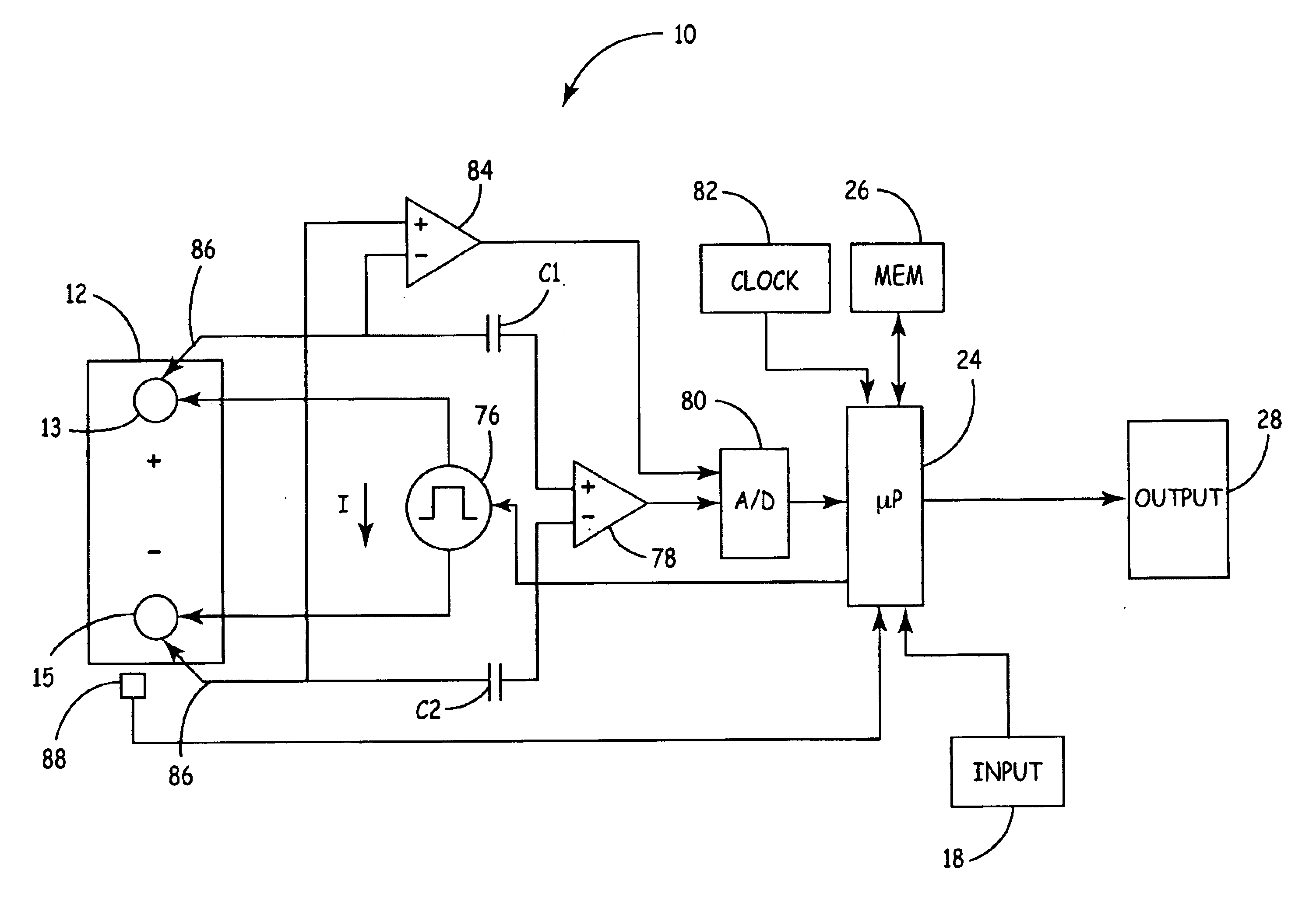
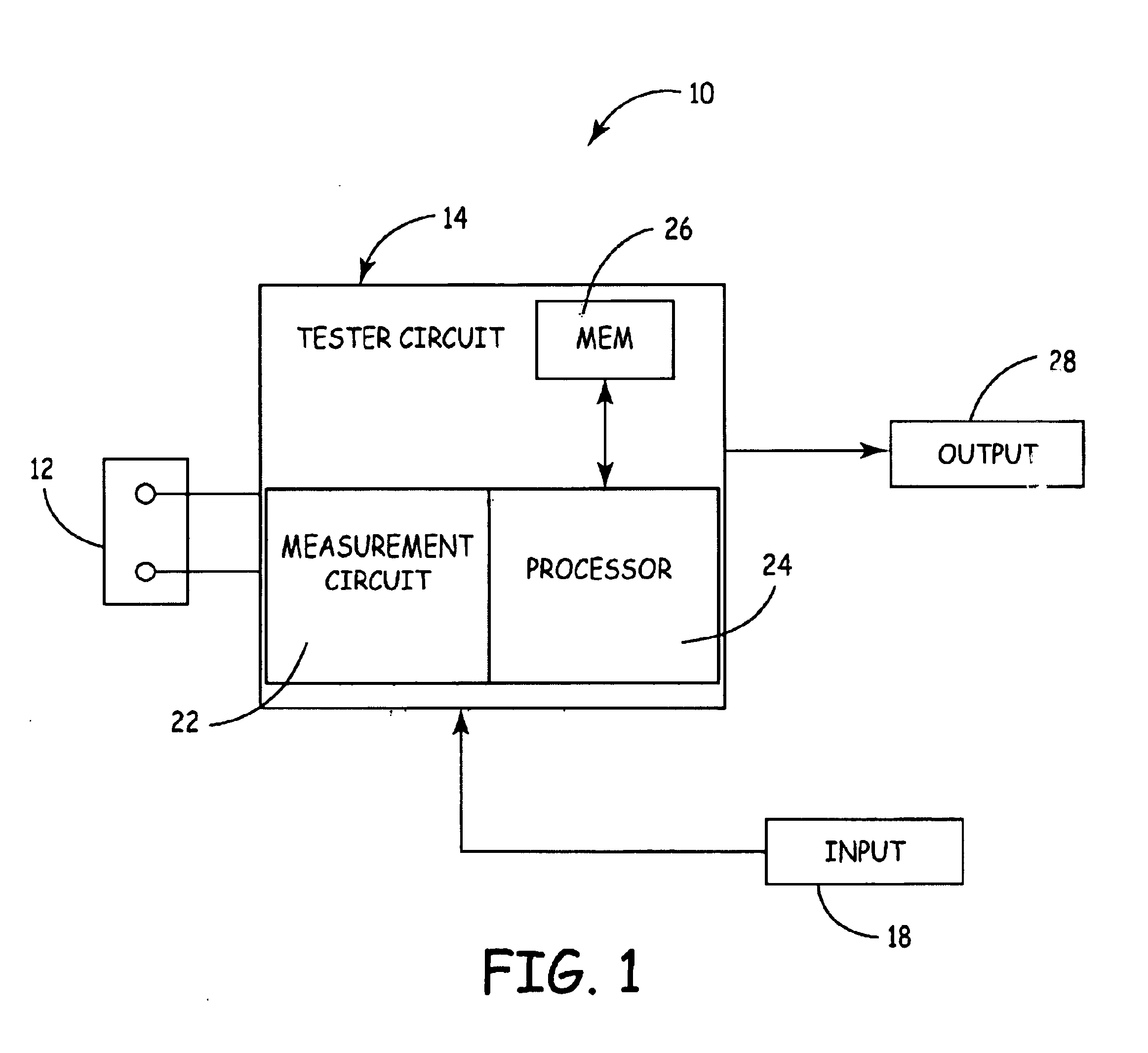
[0011]FIG. 1 is a very simplified block diagram of a battery tester 10 in accordance with an illustrative embodiment of the present invention. The same reference numerals are used in the various figures to represent the same or similar elements. Note that FIG. 1 is a simplified block diagram of a specific type of battery tester. However, the present invention is applicable to any type of battery tester including those which do not use dynamic parameters. Other types of example testers include testers that conduct load tests, current based tests, voltage based tests, tests which apply various conditions or observe various performance parameters of a battery, etc. Battery tester 10 includes a test circuit 14 that dire...


PUM

PropertyMeasurementUnit
voltage potentialaaaaaaaaaa
total voltageaaaaaaaaaa
electricallyaaaaaaaaaa

Abstract

An electronic battery tester, comprising first and second connectors configured to electrically couple to terminals of the battery, a microprocessor configured to test the battery using the first and second connectors, a memory containing a set of locked instructions for the microprocessor, an input configured to receive a software unlocking key, and the microprocessor configured to execute the set of locked instructions in response to the software unlocking key corresponding a predetermined software unlocking key.

Description

BACKGROUND OF THE INVENTION[0001]The present invention relates to storage batteries. More specifically, the present invention relates to a battery system tester for testing storage batteries.[0002]Storage batteries, such as lead acid storage batteries of the type used in the automotive industry, have existed for many years. These storage batteries usually consist of a plurality of individual storage cells electrically connected in series. Typically, each cell has a voltage potential of about 2.1 volts. By connecting the cells in series, the voltage of the individual cells are added in a cumulative manner. For example, in a typical automotive storage battery, six storage cells are used to provide a total voltage when the battery is fully charged up to 12.6 volts.[0003]Several techniques have been used to test the condition of storage batteries. These techniques include a voltage test to determine if the battery voltage is below a certain threshold, and a load test that involves disch...

Claims


Application Information

Patent Timeline
Patent Type & Authority Patents(United States)
IPC IPC(8): G01N27/416G01R31/36
CPCG01R31/3627G01R31/3648G01R31/3668G01R31/385G01R31/379
Inventor SMITH, CLARK E.BERTNESS, KEVIN I.MCSHANE, STEPHEN J.
Owner MIDTRONICS
Why Eureka
Try Eureka