Audio limiting circuit

Active Publication Date: 2006-03-14
PLANTRONICS
View PDF3 Cites 63 Cited by
  • Summary
  • Abstract
  • Description
  • Claims
  • Application Information

AI Technical Summary

Benefits of technology

[0016]In one embodiment the spectral energy detector is comprised of a bandpass filter bank and an average energy detector bank. The bandpass filter bank separates the sound pressure level values into one or more frequency bands. The average energy detector bank determines the acoustic energy associated with each frequency band. The gain logic block calculates intermediate gain values based on whether the acoustic energy associated with each frequency band and the maximum instantaneous amplitude of the predicted sound pressure level exceed certain predetermined limits. The gain logic block then determines a target gain to apply to the unattenuated input signal. In one embodiment, the amount of attenuation applied is the minimum amount of attenuation necessary to comply with the predetermined limit

Problems solved by technology

However, maintaining sound levels below certain predetermined limits by limiting the instantaneous peak voltage using diodes causes significant distortion over a wide range of signal levels.
The result is a degradation of sound quality of the acoustic signal at a level where linearity is desired.
Consequently, the output level of the signal is limited according to the total acoustic energy contained in the signal.
However, the level of the input signal that is uncomfortable is dependent on the frequency content of the signal.
Broad band limiting of speech peaks can result in a

Method used


Image

  • Audio limiting circuit
  • Audio limiting circuit
  • Audio limiting circuit

Examples


Example

[0030]In the following description, for purposes of explanation, numerous specific details are set forth in order to provide a thorough understanding of the invention. The arts of digital signal processing and acoustic engineering are such that many different variations of the illustrated and described features of the invention are possible. Those skilled in the art will undoubtedly appreciate that the invention can be practiced without some specific details described below, and indeed will see that many other variations and embodiments of the invention can be practiced while still satisfying the teachings of the invention.

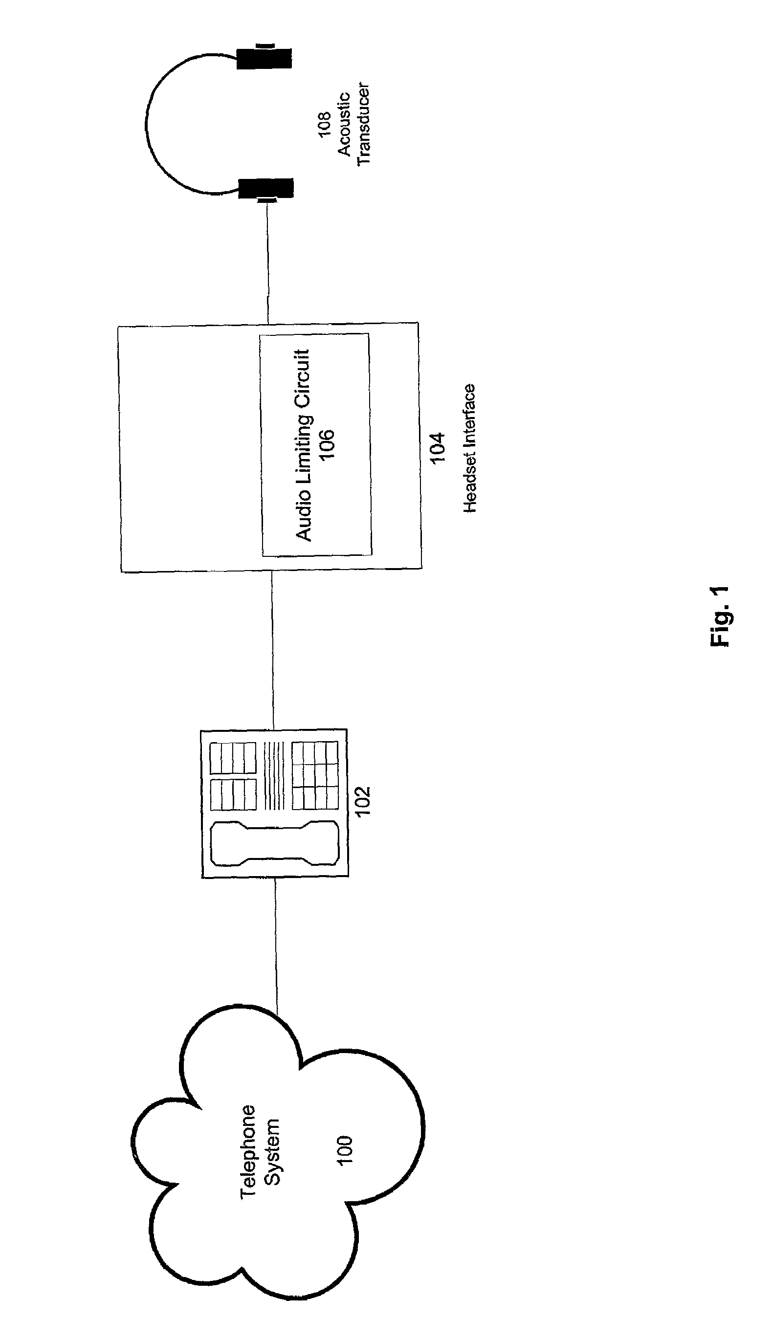
[0031]FIG. 1 shows one implementation of the present invention in combination with a telephone communication system to provide audio signal limiting characteristics. A telephone 102, which itself is connected to a telephone network 100, is connected to a headset interface 104 containing an audio limiting circuit 106 in accordance with one embodiment of the present...


PUM


Abstract

An audio limiting circuit capable of satisfying frequency dependent limits and time domain constraints, is disclosed. In one illustrative embodiment, an input node receives an unattenuated input signal and a system modeling filter predicts the amount, if any, by which the sound pressure level that would be generated by an acoustic transducer in response to the unattenuated input signal, would exceed one or more predetermined limits. In that embodiment, an energy detector separates the excess predicted sound pressure level into one or more frequency bands and calculates the average acoustic energy associated with each band. A gain logic block determines an attenuation factor based on whether one or more of the predetermined limits has been exceeded and the attenuation factor values are smoothed to minimize abrupt changes to the unattenuated input signal. A delay buffer delays the unattenuated input signal values. Finally, in the embodiment described here, the smoothed attenuation factor values are synchronized with and applied to the delayed input signal values and the resulting attenuated signal is transmitted to an output node and ultimately to one or more acoustic transducers.

Description

BACKGROUND[0001]A. Field of the Invention[0002]This invention relates to the fields of acoustic engineering and digital signal processing, and more particularly to techniques for filtering and limiting acoustic signals, so as to maintain the sound pressure levels and acoustic energy associated with such signals within certain predetermined limits.[0003]B. Description of the Related Art[0004]Advanced telecommunication headsets and their related circuitry typically provide some method of limiting the maximum sound level that the speakers can produce. Traditional approaches to implementing these limiting circuits have focused on limiting the peak voltage of very fast transient signals as well as limiting signals sustained above a reference level over longer time periods. These signals are electrical representations of the desired acoustic signal.[0005]Existing products and techniques implement signal limiting using analog circuitry such as diodes to provide instantaneous peak limits on...

Claims


Application Information

Patent Timeline
IPC IPC(8): H03G5/00G10L19/14H03G3/00
CPCH03G9/025H03G9/005
Inventor WEEKS, WILLIAM A.MORRELL, WILLIAM R.
Owner PLANTRONICS
Why Eureka
Try Eureka