Bed rail assembly

a bed rail and assembly technology, applied in the direction of rod connections, fluid mattresses, sofas, etc., can solve the problems of difficult assembly/disassembly of the bed rail by the general consumer, and a large number of parts forming a complicated mechanism

Active Publication Date: 2006-03-21
WU SUNG TSUN
View PDF3 Cites 41 Cited by
  • Summary
  • Abstract
  • Description
  • Claims
  • Application Information

AI Technical Summary

Problems solved by technology

Nevertheless, the conventional rail assembly has a great number of parts forming a complicated mechanism.
It is not easy for the general consumers to assemble / disassemble the bed rail.

Method used


Image

  • Bed rail assembly
  • Bed rail assembly
  • Bed rail assembly

Examples


Embodiment Construction

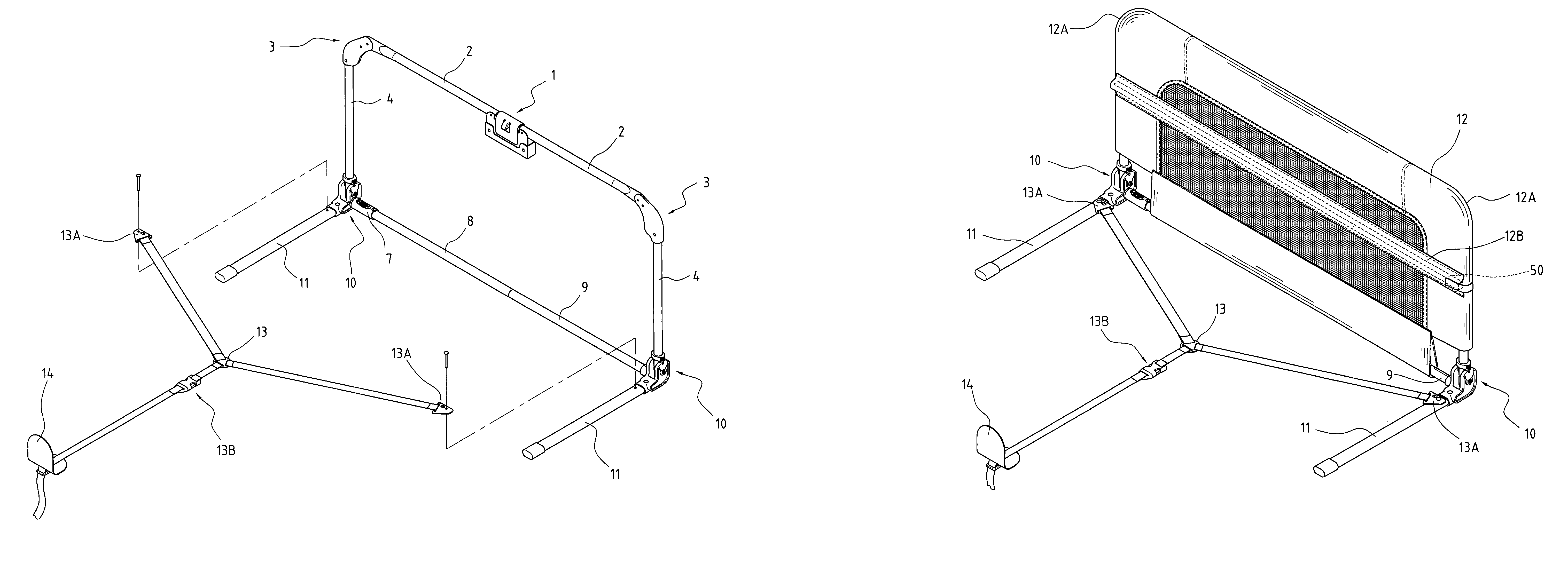
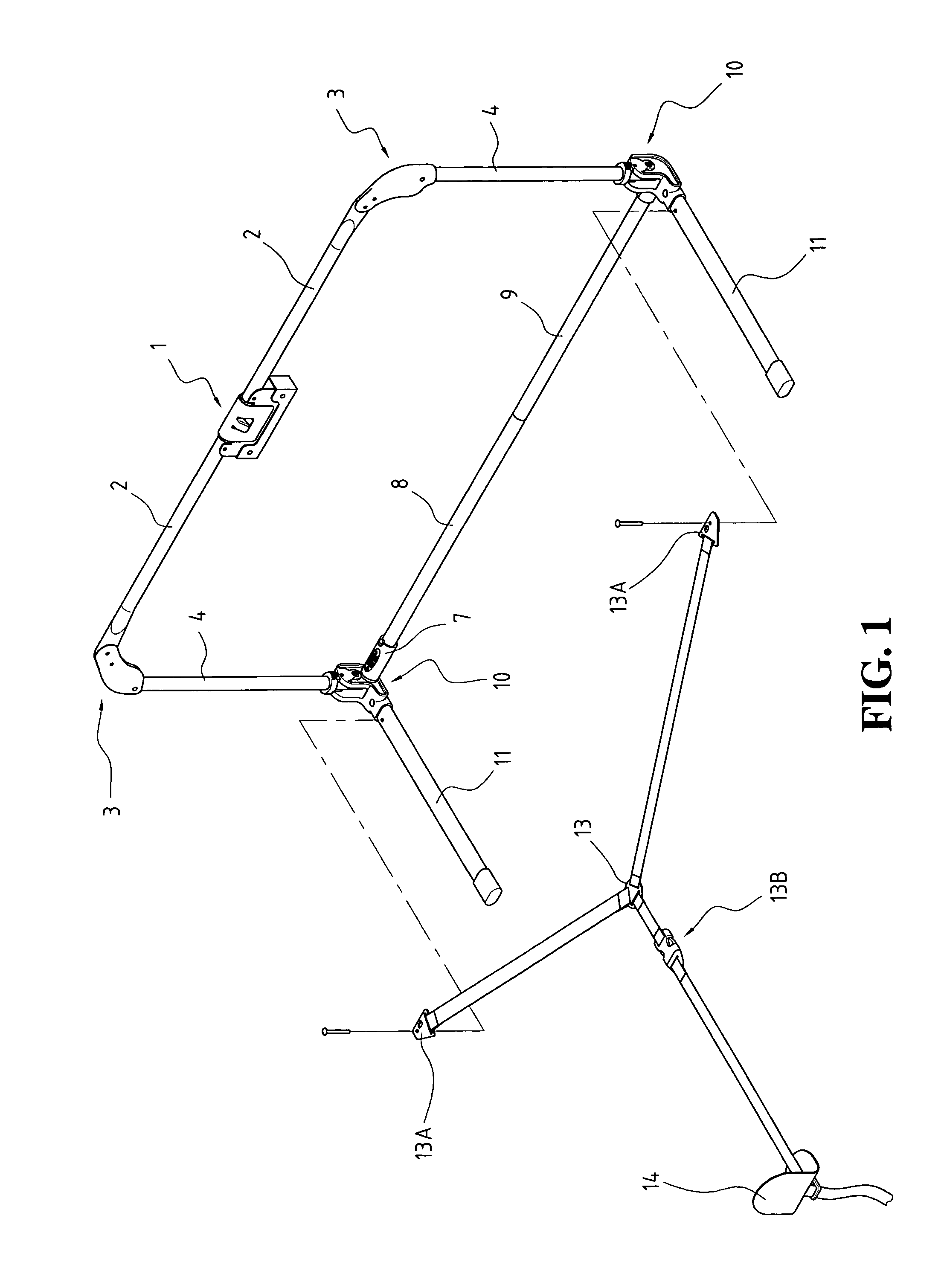
[0016]Referring to the drawings and in particular FIGS. 1 and 3, a bed rail assembly constructed in accordance with the present invention comprises a joint device 1 that is arranged between and pivoted to opposing ends of two top tubes 2. Each top tube 2 has a flat free end. The joint device 1 has a release button 100, which, when actuated, releases the top tubes 2 from the joint device 1 to allow the top tubes 2 to rotate in the direction designated by arrows A in FIG. 3 thereby folding the bed rail assembly to a compact size as shown in FIG. 8. The joint device 1 can be any known device that allows for folding and no further detail will be given hereinafter.

[0017]A substantially L-shaped corner member 3 is connected to the free end of each top tube 2. The corner member 3 has a clamp end 31 extending in a horizontal direction and pivoted to the free end of the top tube 2 and a receiving end 32 extending in a vertical direction to receive an end of a vertical tube 4 therein. A first...


PUM


Abstract

A bed rail assembly includes a joint device connecting two top tubes, a pair of corner members mounted to free ends of the top tubes, two vertical tubes mounted to and depending from the corner members, and a pair of knuckle devices mounted to lower ends of the vertical tubes. Horizontal support tubes extend from the knuckle devices in a direction substantially normal to a plane defined by the top tubes and the vertical tubes. Extensions project from the knuckle devices to receive and fix support tube thereby forming a rectangular frame onto which a cover is attached to shield the frame. Each knuckle device includes a movable member movably connected to a base of the knuckle device to allow collapse of the bed rail. A Y-shaped belt and an L-shaped retention member are used to secure the bed rail assembly to a mattress.

Description

BACKGROUND OF THE INVENTION[0001]1. Field of the Invention[0002]The present invention relates to a bed rail assembly that can be easily assembled and / or disassembled.[0003]2. The Related Art[0004]A conventional bed, especially a baby bed, generally includes rails on at least one side of the bed to prevent the baby from falling from the bed. A bed rail assembly that is currently available in the market is usually foldable for easy transportation and storage for it occupies a small amount of space after folded. Nevertheless, the conventional rail assembly has a great number of parts forming a complicated mechanism. It is not easy for the general consumers to assemble / disassemble the bed rail.[0005]Thus the present invention is aimed to provide a bed rail assembly that can be easily assembled / disassembled. Further, the bed rail assembly of the present invention comprises a cover to shield moving parts thereof, which prevents a user from being damaged by the movement of the moving parts...

Claims


Application Information

Patent Timeline
Patent Type & Authority Patents(United States)
IPC IPC(8): A47C21/08A47D15/00
CPCA47C21/08A47D15/008A61G7/0507A61G2007/051A61G2007/0518Y10T403/551Y10T403/7021Y10T403/32361Y10T403/32368Y10T403/32106Y10T403/32344Y10T403/4694A61G7/051A61G7/0518F16B2200/10
Inventor WU, SUNG-TSUN
Owner WU SUNG TSUN
Why Eureka
Try Eureka