
Stent with stepped connectors

a connector and stent technology, applied in the field of stents with stepped connectors, can solve the problems of new challenges in the field of stent design, and the difficulty of uniform coating of conventional bare stent designs

Inactive Publication Date: 2007-02-20
BOSTON SCI SCIMED INC
View PDF68 Cites 37 Cited by
  • Summary
  • Abstract
  • Description
  • Claims
  • Application Information

AI Technical Summary

Benefits of technology

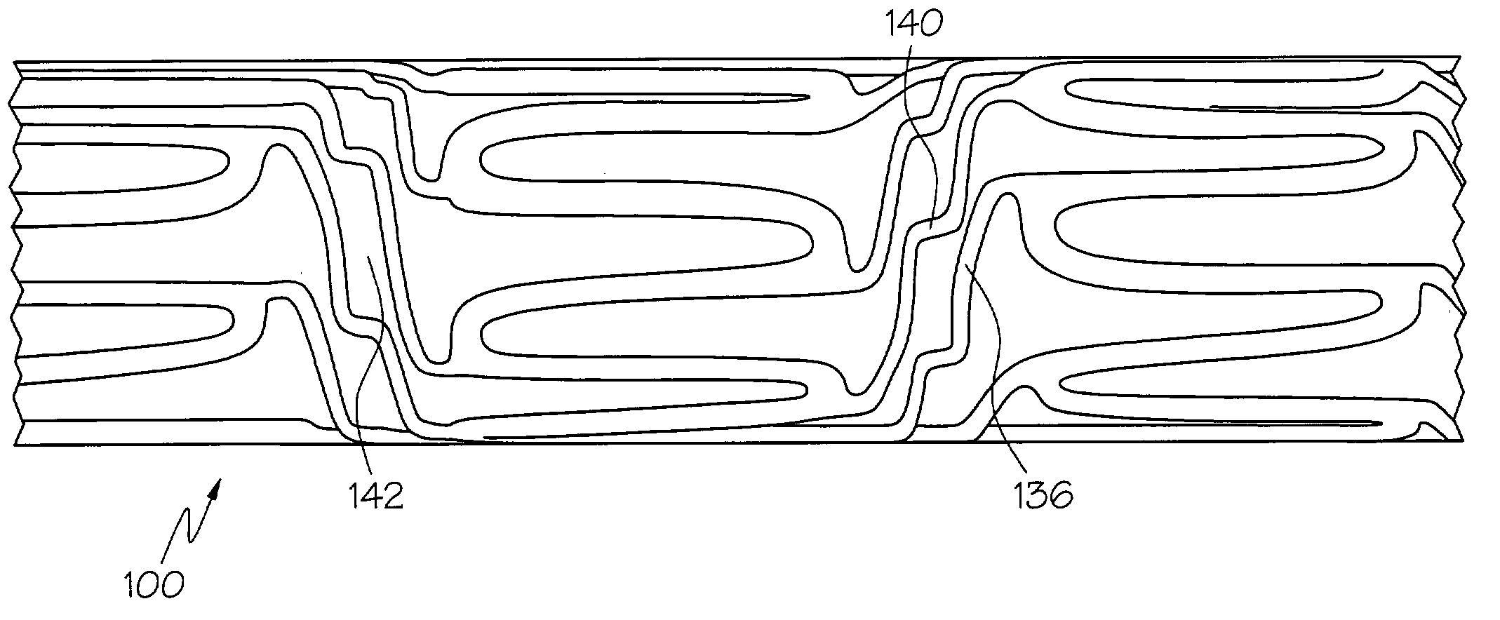
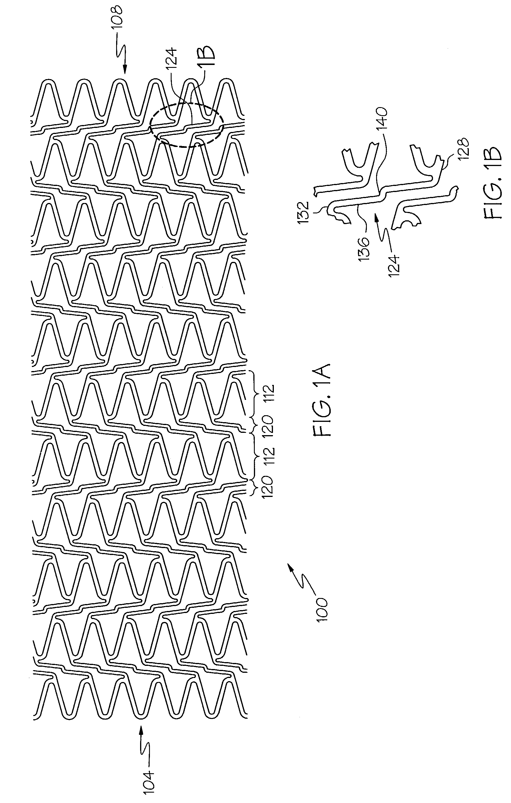
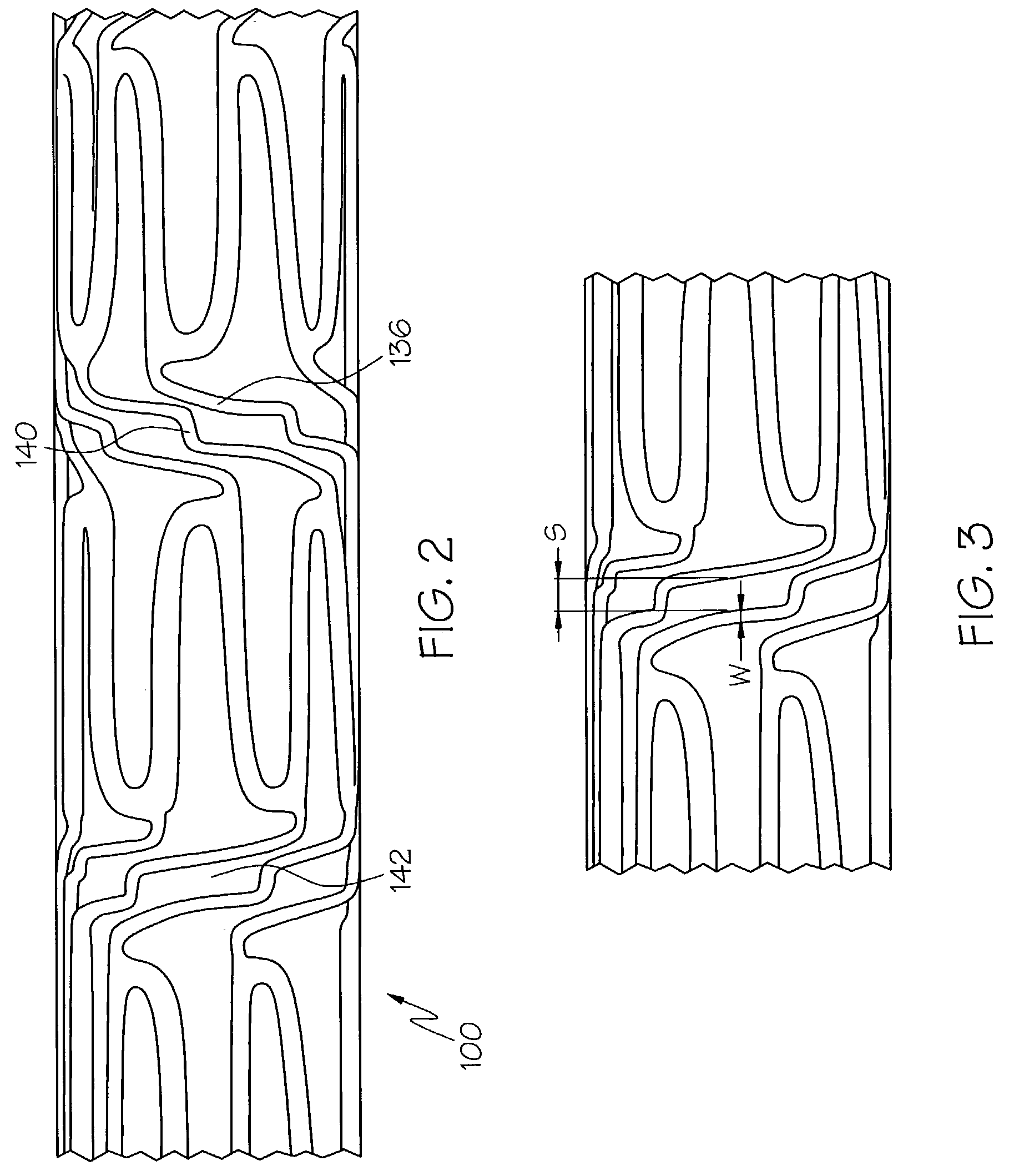
[0006]In one embodiment, the invention is directed to a stent comprising a plurality of serpentine circumferential bands, and a plurality of connector columns. Each connector column is located between two adjacent circumferential bands and comprises one or more connector struts. Each connector strut is connected at one end to one serpentine circumferential band and at another end to another serpentine circumferential band. Each connector strut further comprises step and riser elements. Desirably each connector strut comprises only two step sections and no more than three riser elements.

Problems solved by technology

The presence of drug-coatings on stents, however, presents new challenges in the area of stent design.
Conventional bare stent designs may prove difficult to coat uniformly because of the proximity of different structural features.

Method used


Image

  • Stent with stepped connectors
  • Stent with stepped connectors
  • Stent with stepped connectors

Examples


Embodiment Construction

[0013]While this invention may be embodied in many different forms, there are described in detail herein specific embodiments of the invention. This description is an exemplification of the principles of the invention and is not intended to limit the invention to the particular embodiments illustrated.

[0014]For the purposes of this disclosure, like reference numerals in the figures shall refer to like features unless otherwise indicated.

[0015]In one embodiment, the invention is directed to a stent such as that shown generally at 100 in FIG. 1a, having a first free end 104 and a second free end 108, comprising a plurality of serpentine circumferential bands 112, and a plurality of connector columns 120. Each serpentine circumferential band 112 may form a plurality of alternating peaks and troughs. Each connector column 120 is located between two adjacent serpentine circumferential bands 112 and comprises one or more connector struts 124. Each connector strut 124 is connected at one e...


PUM


Abstract

A stent comprises a plurality of serpentine circumferential bands and a plurality of connector columns. Each connector column is located between two adjacent serpentine circumferential bands and comprises a plurality connector struts. Each connector strut is connected at one end to one serpentine circumferential band and at another end to another serpentine circumferential band. Each connector strut has step sections and at least one riser. Each step section extends substantially in a circumferential direction and each riser extends in a substantially longitudinal direction. The steps in a connector are connected to one another via a riser.

Description

BACKGROUND OF THE INVENTION[0001]The use of stents in bodily lumen is well known. A stent is typically delivered in an unexpanded state to a desired location in a bodily lumen via a stent delivery device such as a catheter. Once the stent is at the desired bodily location, it is either expanded with a balloon or other suitable device or allowed to expand by, for example, withdrawing a restraining sheath. Typically, the stent is delivered bare to the body. During the past several years, however, there has been a great deal of interest in drug-coated stents. Specifically, a number of drug-coated stents have been developed which allow for time-release of a drug. These stents are believed to offer the possibility of reduced restenosis. The presence of drug-coatings on stents, however, presents new challenges in the area of stent design. Conventional bare stent designs may prove difficult to coat uniformly because of the proximity of different structural features.[0002]There is a need fo...

Claims


Application Information

Patent Timeline
Patent Type & Authority Patents(United States)
IPC IPC(8): A61F2/06A61F2/90
CPCA61F2/91A61F2/915A61F2230/0054A61F2002/91558A61F2002/91533
Inventor LENZ, JASON T.
Owner BOSTON SCI SCIMED INC
Learn More