Fluid filter element

a technology of filter elements and components, applied in the direction of cartridge filters, filtration separation, separation processes, etc., can solve the problems of contaminants reaching the components downstream in the fuel system, changing filter elements may pose problems, and collecting impurities to fall off the elements, so as to facilitate the easy grasping of the spent filter elements. , the effect of easy access

Active Publication Date: 2009-05-12
WIX FILTRATION
View PDF38 Cites 38 Cited by
  • Summary
  • Abstract
  • Description
  • Claims
  • Application Information

AI Technical Summary

Benefits of technology

[0085]When it is desirable to change a spent filter element, the lid 16 is removed (screwed off), and the filter element 140 can be easily accessed and replaced with a fresh filter element. To facilitate the easy grasping of the spent filter element, the flow control valve 132 automatically pushes the spent filter element 140 outwardly a short distance by resilience of the spring 135. This also allows at least some of the fluid to drip off the filter element and remain in the filter housing 112, rather than drip onto the surrounding area during filter element removal.

Problems solved by technology

Replacing the element also ensures that impurities are removed from fuel before it is delivered to other fuel system components such as fuel injection pumps and fuel injectors, where such contaminants may cause severe damage.
Changing filter elements may pose problems however.
One common problem is that disturbance of the spent element during replacement may cause collected impurities to fall off the element.
As a result these contaminants may reach the components downstream in the fuel system.
Another problem with certain prior art fuel filter constructions is that changing the element may require a mechanic to have skin contact-with the fuel.
While known liquid filters have proven to be acceptable for various vehicular applications, such devices are nevertheless susceptible to improvements that may enhance their performance and cost.

Method used


Image

  • Fluid filter element
  • Fluid filter element
  • Fluid filter element

Examples


Embodiment Construction

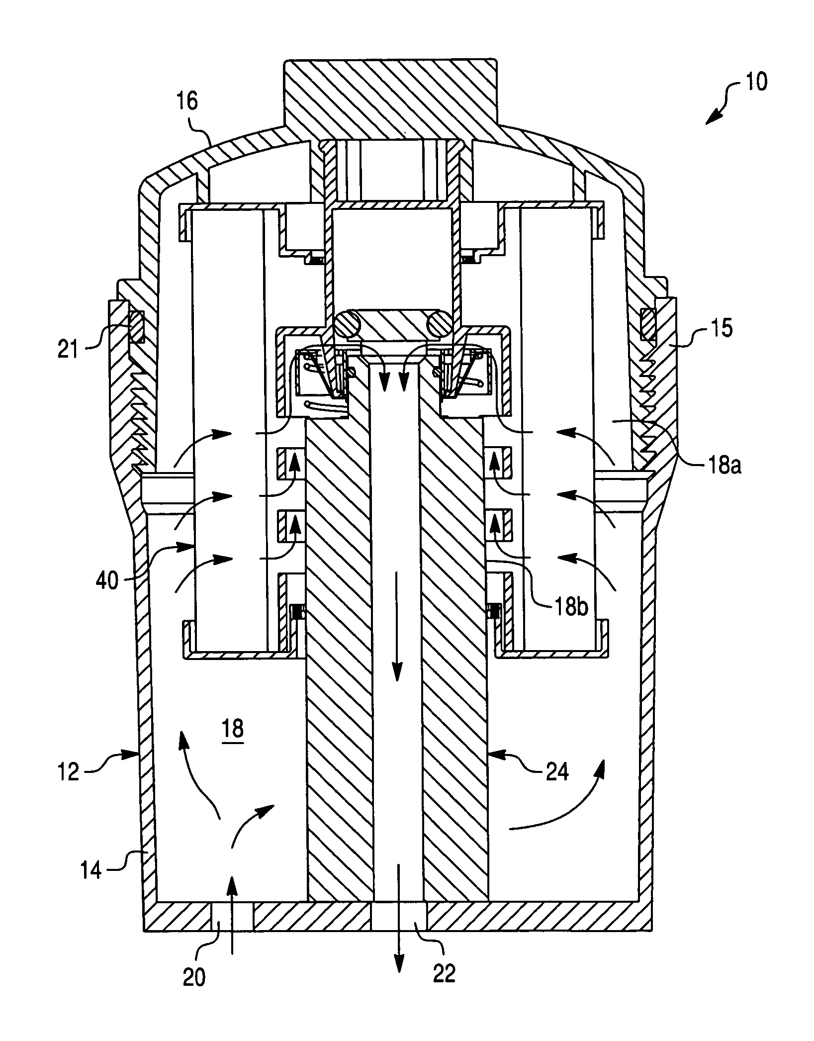
[0040]The preferred embodiment of the present invention will now be described with the reference to accompanying drawings. For purposes of the following description, the terms “upper”, “lower”, “top”, “bottom”, “upward”, “downward”, “vertical”, “horizontal” and derivatives of such terms shall relate to the invention as oriented in FIG. 1. However, it is to be understood that the invention may assume various alternative orientations, except where expressly specified to the contrary. It is also to be understood that the specific devices and processes illustrated in the attached drawings, and described in the following specification are simply exemplary embodiments of the inventive concepts. Specific dimensions and other physical characteristics relating to the embodiments disclosed herein are not to be considered as limiting, unless expressly stated otherwise.

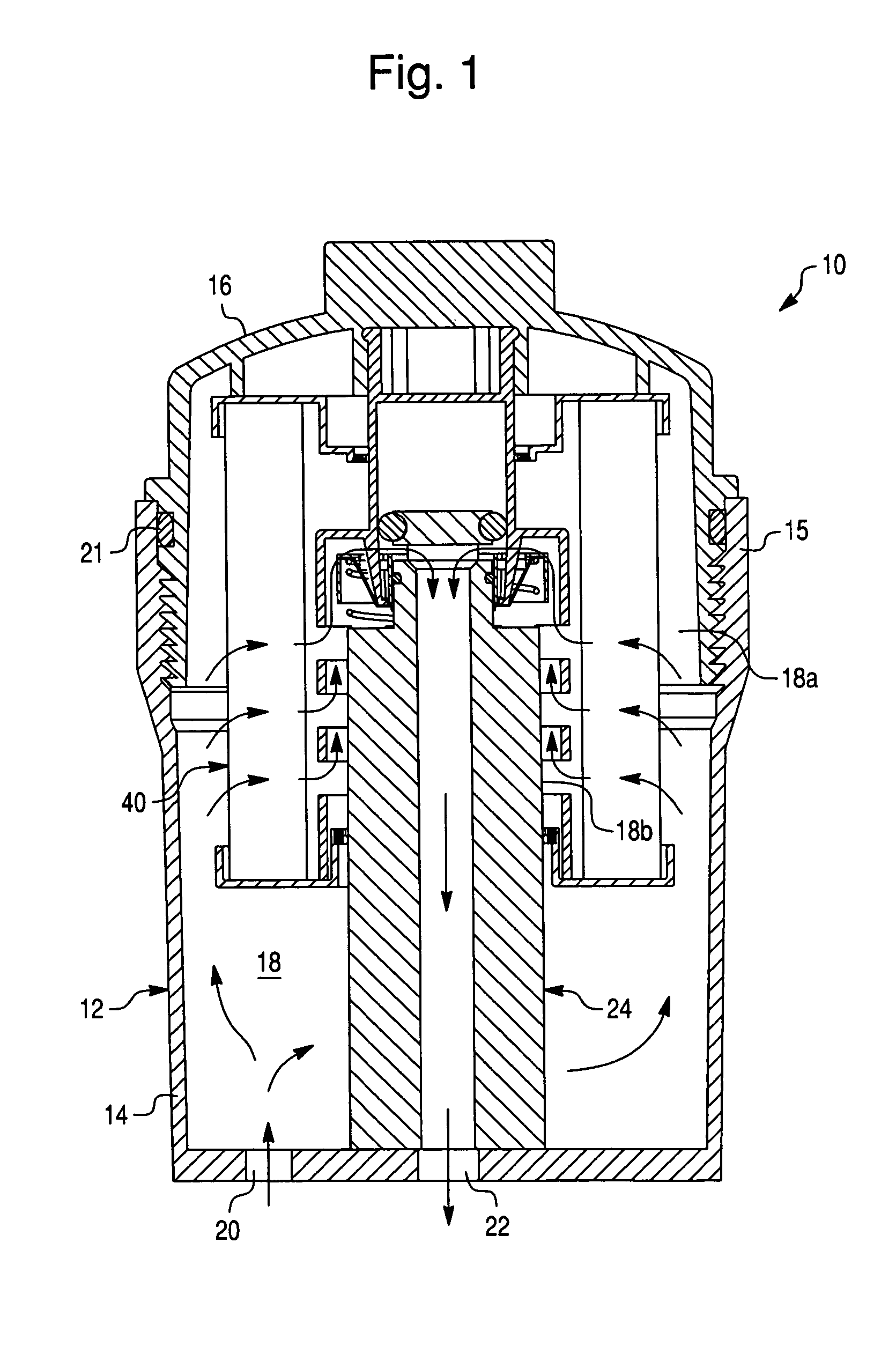
[0041]FIG. 1 depicts a fluid filter assembly 10 in accordance with the first exemplary embodiment of the present invention prov...


PUM

PropertyMeasurementUnit
diameteraaaaaaaaaa
areaaaaaaaaaaa
physical characteristicsaaaaaaaaaa

Abstract

A filter element is removably positionable within a filter housing that includes a standpipe extending therewithin and provided with a flow control valve. The filter element comprises a tubular filter media, a first end cap, a second end cap longitudinally spaced from the first end cap, and a center tube extending between the first and second end caps. The center tube has a substantially cylindrical body extending between opposite first and second ends of the center tube. The center tube has at least one inlet opening formed on the cylindrical body and a standpipe opening at the second end thereof adjacent to the second end cap through which the standpipe may be inserted longitudinally into the center tube. The center tube further has at least one actuator key provided to open the flow control valve of the standpipe.

Description

BACKGROUND OF THE INVENTION[0001]1. Field of the Invention[0002]This invention relates to fluid filter assemblies in general, and, more particularly, to a fluid filter assembly including a replaceable, fluid filter element that actuates a flow control valve in a standpipe of a filter housing.[0003]2. Description of the Prior Art[0004]Many types of fluid filters are known in the prior art. A popular type of fluid filter construction is one that has a housing which encloses a replaceable filter element. Fluid, such as oil or fuel, is cleansed of impurities as it passes through filter media of the filter element. The filter media captures many of the impurities that are removed from the fluid. Other impurities collect on the surface of the media and fall downward into a bottom area of the filter housing from which they may be periodically removed through a drain valve.[0005]Periodically the filter element must be replaced. Such periodic replacement ensures that the filter element will ...

Claims


Application Information

Patent Timeline
Patent Type & Authority Patents(United States)
IPC IPC(8): B01D35/153B01D35/157
CPCB01D35/153B01D29/11B01D2201/0415B01D2201/305B01D2201/316B01D2201/4046
Inventor STAMEY, JR., WILLIE L.ROLL, MARK ALLEN
Owner WIX FILTRATION
Why Eureka
Try Eureka