Multi-cylinder wind powered generator

a generator and multi-cylinder technology, applied in the direction of electric generator control, renewable energy generation, greenhouse gas reduction, etc., can solve the problems of not appearing to be going very fast, rotors are heavy, and require a fair amount of wind, so as to achieve convenient and efficient operation and design.

Inactive Publication Date: 2008-09-16
KETCHAM JOHN C
View PDF56 Cites 36 Cited by
  • Summary
  • Abstract
  • Description
  • Claims
  • Application Information

AI Technical Summary

Benefits of technology

[0006]A primary objective of the present invention is to provide a wind generator having improved features facilitating convenient and efficient operation and design for utilizing wind power.
[0008]Yet another objective of the present invention to provide a device that does not need to be so high above the ground as is the case with conventional windmill fans.
[0009]Still another objective of the present invention is to provide a device that can receive air flow from any direction without requiring repositioning with a wind direction change.
[0010]Yet still another objective of the present invention is to provide a device which emits a whirling sound which is more restrained and more easily tolerated than conventional windmill sounds.
[0011]A further objective of the present invention is to provide a device that can be made more esthetically acceptable by being attractively lighted to enhance appearance and permit relatively easy location at night.
[0015]The top cylinder is attached to the longest supporting and rotating member, a post, and at the bottom of that post is a gearing mechanism which turns a dynamo. On the outside of this post is a first tube to which the second cylinder is attached. It rotates independently of the post and also has a gearing mechanism at the bottom which turns a dynamo. A second tube is outside the first tube and attaches to the lowest cylinder. It operates similarly to the first sleeve. There are ball bearing rings between the post and the first tube for separation and sturdiness which allow the post and that tube to rotate with a minimum of friction. Similarly, there are ball bearing rings between the first tube and the second tube which accomplish the same result. Suspended over all three cylinders is a mesh cage whose purpose is to protect the cylinders from heavy hail and other adverse weather conditions and to prevent birds from crashing into the moving cylinders and sustaining injuries.

Problems solved by technology

The rotors are heavy and require a fair amount of wind to get them moving.
When they move, they do not appear to be going very fast because they are so big.
However, they are going fast enough to create considerable noise in the form of a whomp, whomp, whomp.
They are high enough and going fast enough to pose a danger to birds, and they do kill birds much to the dismay of environmentalists.
They are additionally complicated in that the rotors must be properly positioned to catch the wind effectively.
With a wind that is gusting from several different directions, there are inefficiencies.

Method used


Image

  • Multi-cylinder wind powered generator
  • Multi-cylinder wind powered generator
  • Multi-cylinder wind powered generator

Examples


Embodiment Construction

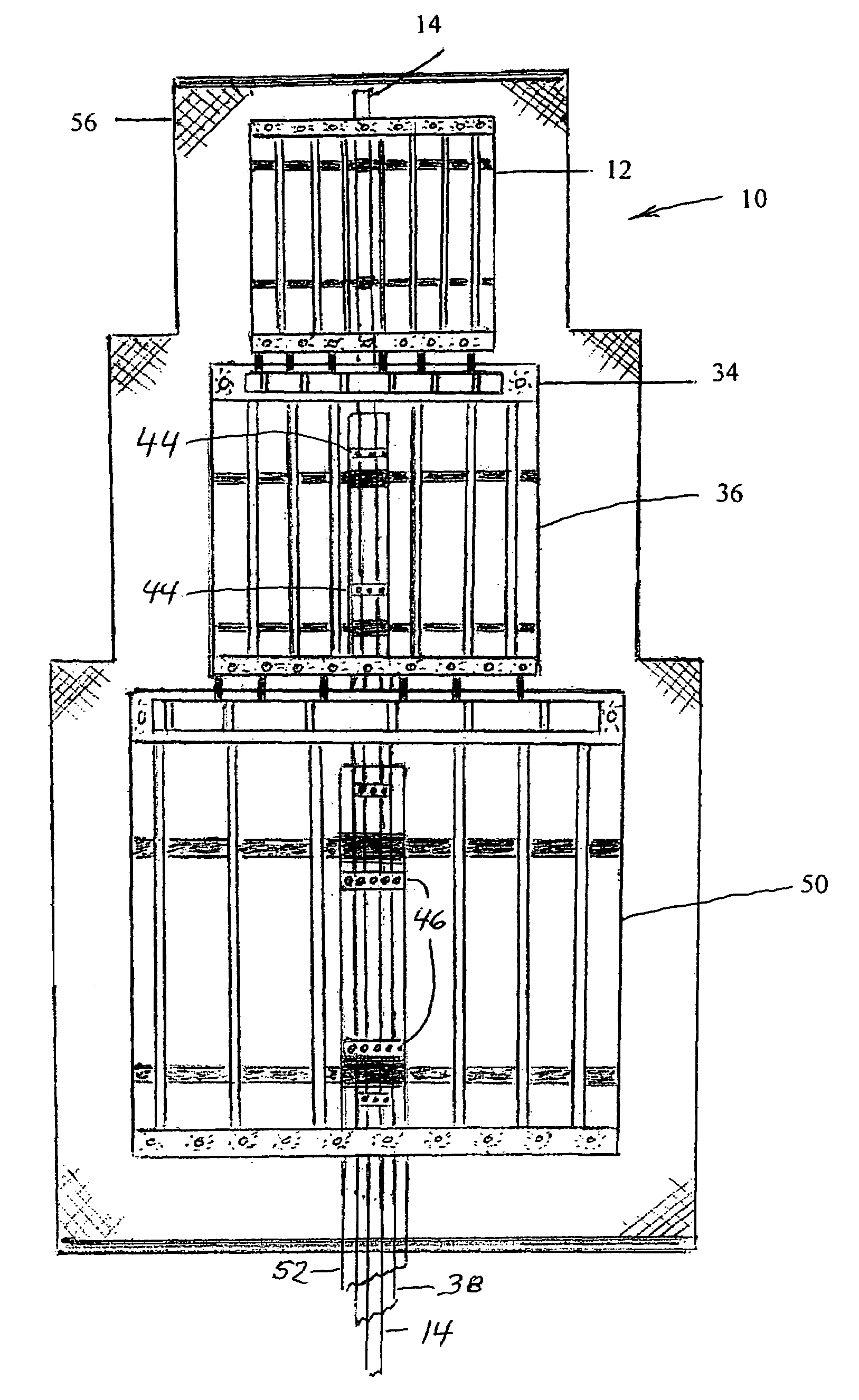
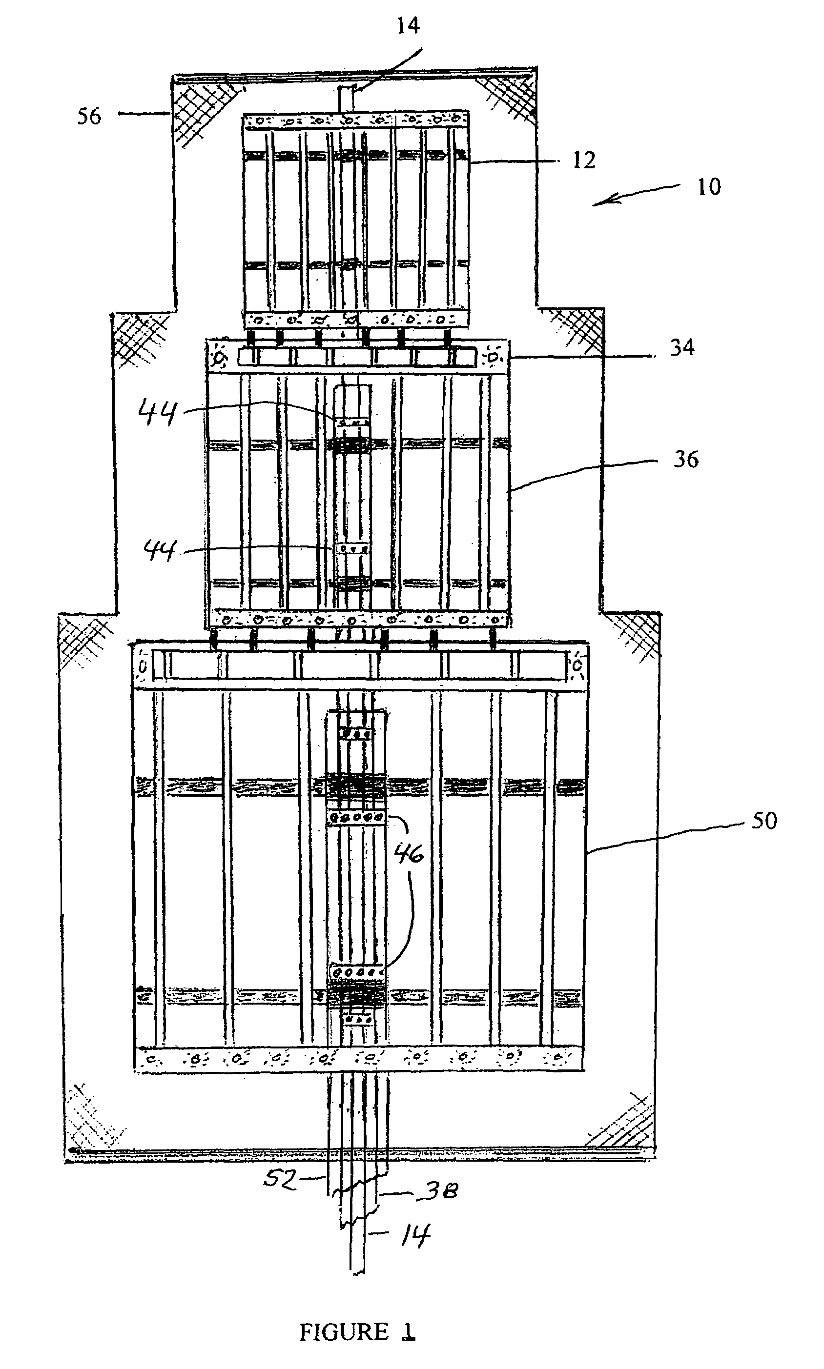
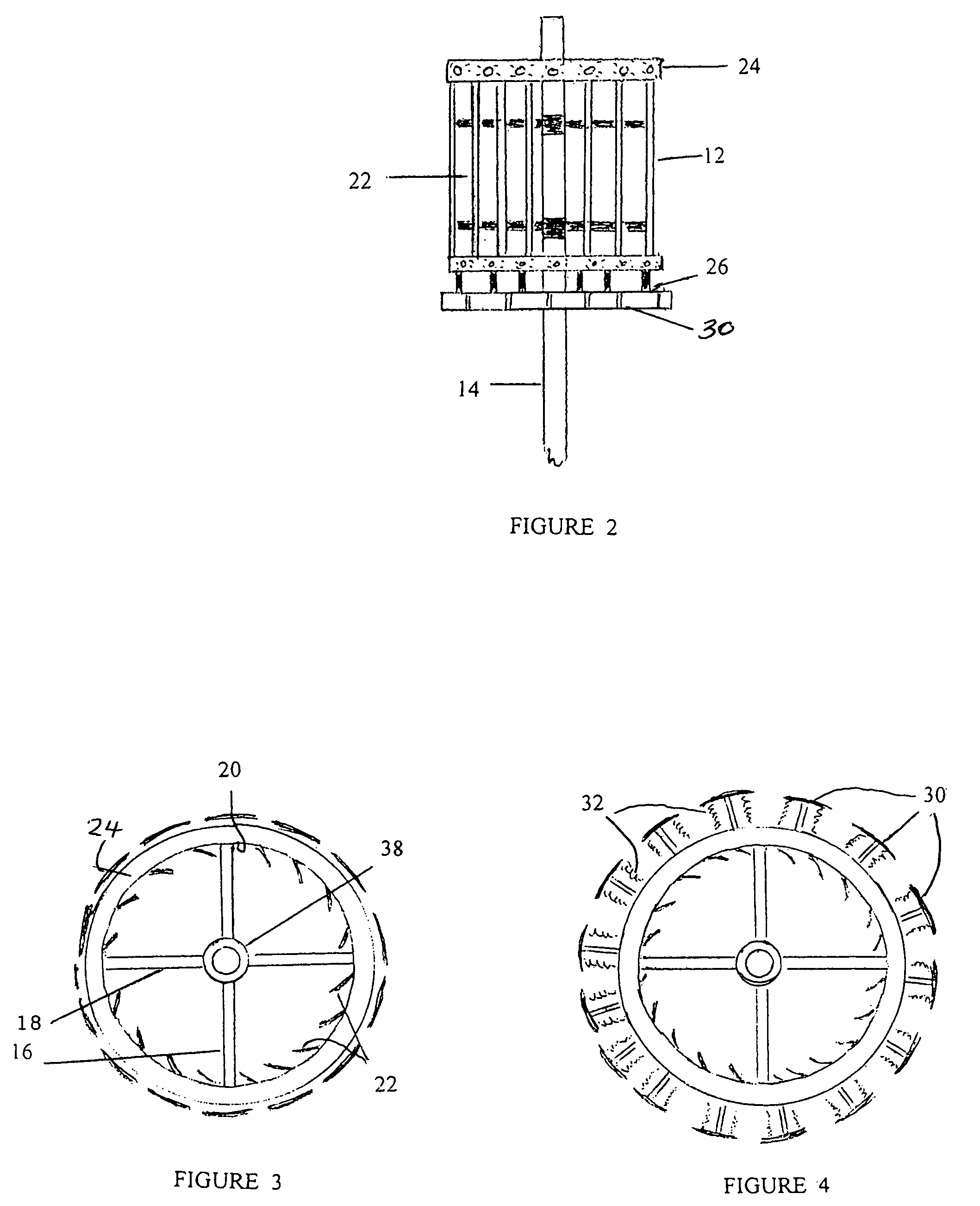
[0028]Referring now to the drawings and particularly to FIG. 1, a generating device shown generally as 10 includes a first squirrel cage cylinder 12 which is attached to a post 14 by braces 16, 18 that extend to the inner perimeter 20 of cylinder 12. A plurality of fins 22 are secured to and between circular end rings 24, 26 in a fixed relationship.

[0029]Cylinder ring 26 supports clutch plates 30. When cylinder 12 is not rotating rapidly, retracting springs 32 hold plates 30 to ring 26, thus allowing ring 26 to fit freely inside the top ring 34 of second cylinder 36. As wind rotates cylinder 12 at a faster rate, centrifugal force pushes clutch plates 30 outwardly so that they engage the inner perimeter 35 of top ring 34 of second cylinder 36 and cause it to rotate. As wind decreases, clutch plates 30 retract and second cylinder 36 stops moving. FIG. 4 illustrates clutch plates 30 of cylinder 12 in the extended, rim-engaging position.

[0030]Second cylinder 36 is attached to a first tu...


PUM


Abstract

A multiple generator having a vertical post and multiple vertical tubes has the generators positioned vertically one above the other. Each is cylindrical in shape and has two rings separated by connecting fins. The cylinders vary in size with the top being the smallest, the middle or second being larger and the third being the largest. With low winds, only the smallest generator turns. As wind velocity increases, the small generator rotates faster until clutches in a clutch ring move outwardly until they engage and secure to the second generator so both generators move together. As wind speed increases, clutches on the second generator move outwardly until they engage and secure to the third generator and all generators now rotate together. Thus varying amounts of electricity are generated depending on the wind speed and which generators are active. Each generator has its own rotating shaft with ball bearings between the post and first tube and between the first and second tubes. A cage protects the device from birds or other air-suspended articles.

Description

BACKGROUND OF THE INVENTION[0001]1. Field of the Invention[0002]The present invention relates to wind powered generators and, more particularly, to multi-cylinder vertically positioned wind powered generators having the ability to utilize low wind speeds to commence generating some electricity and to increasingly utilize higher wind speeds to substantially increase generating capacity.[0003]2. Description of the Prior Art[0004]Conventional wind powered generators in place today generally have three rotors with each being nearly as long as the wing of a small airplane. The rotors are heavy and require a fair amount of wind to get them moving. To capture the wind, the rotors are placed on very high towers. When they move, they do not appear to be going very fast because they are so big. However, they are going fast enough to create considerable noise in the form of a whomp, whomp, whomp. They are high enough and going fast enough to pose a danger to birds, and they do kill birds much ...

Claims


Application Information

Patent Timeline
Patent Type & Authority Patents(United States)
IPC IPC(8): F03D9/00H02P9/04
CPCF03D3/005F05B2240/211F05B2240/40Y02E10/74F05B2250/315F05B2260/4023F05B2250/231F03D3/02
Inventor KETCHAM, JOHN C.
Owner KETCHAM JOHN C
Why Eureka
Try Eureka