Accumulator tank assembly and method

a technology of accumulator tank and accumulator tank, which is applied in the direction of transportation and packaging, rigid containers, mechanical equipment, etc., can solve the problems of increasing the difficulty of maintaining clean and sanitary conditions in the accumulator tank, and the accumulator tank can remain fluid for relatively long periods of tim

Active Publication Date: 2006-03-21
SHURFLO
View PDF31 Cites 23 Cited by
  • Summary
  • Abstract
  • Description
  • Claims
  • Application Information

AI Technical Summary

Problems solved by technology

During extended periods of low demand, fluid can remain in the bladder of an accumulator tank for relatively long periods of time.
The tendency of

Method used


Image

  • Accumulator tank assembly and method
  • Accumulator tank assembly and method
  • Accumulator tank assembly and method

Examples


Embodiment Construction

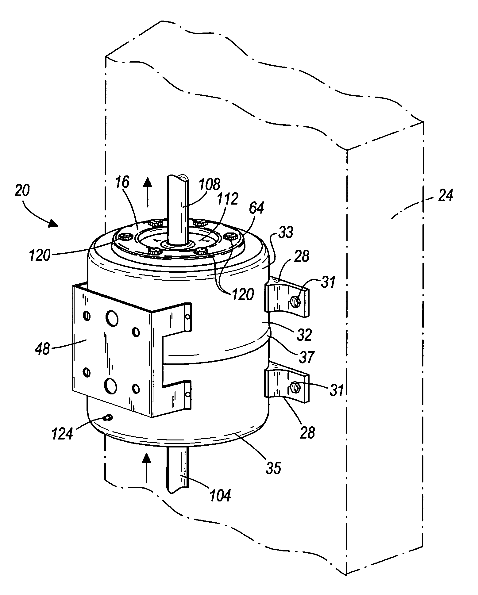
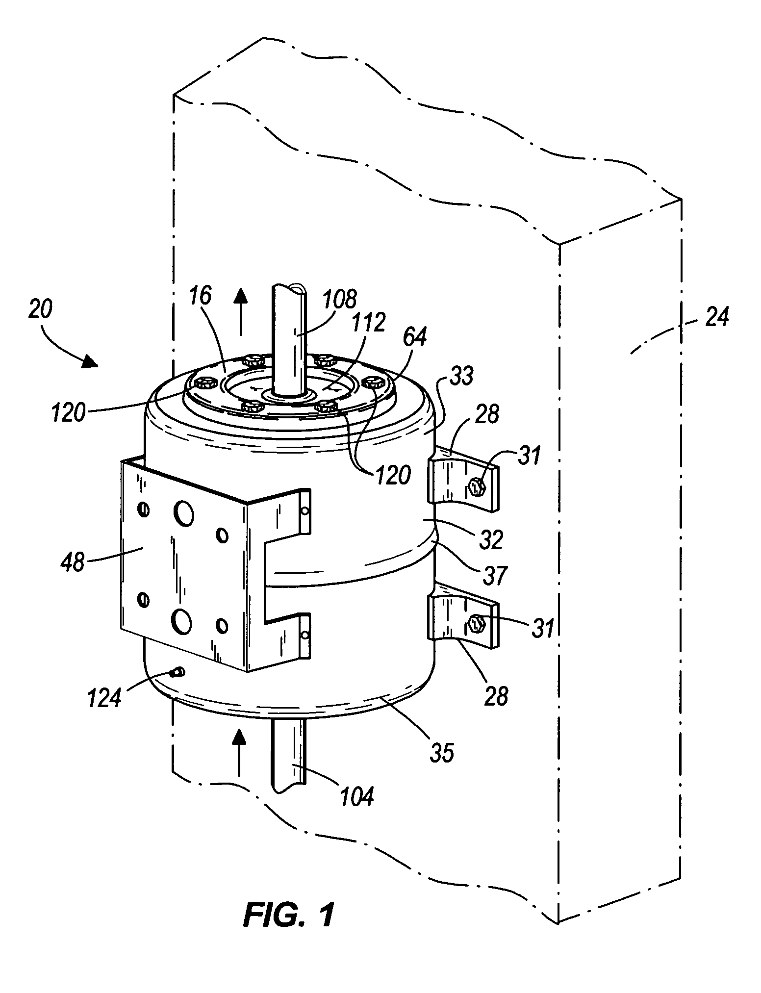
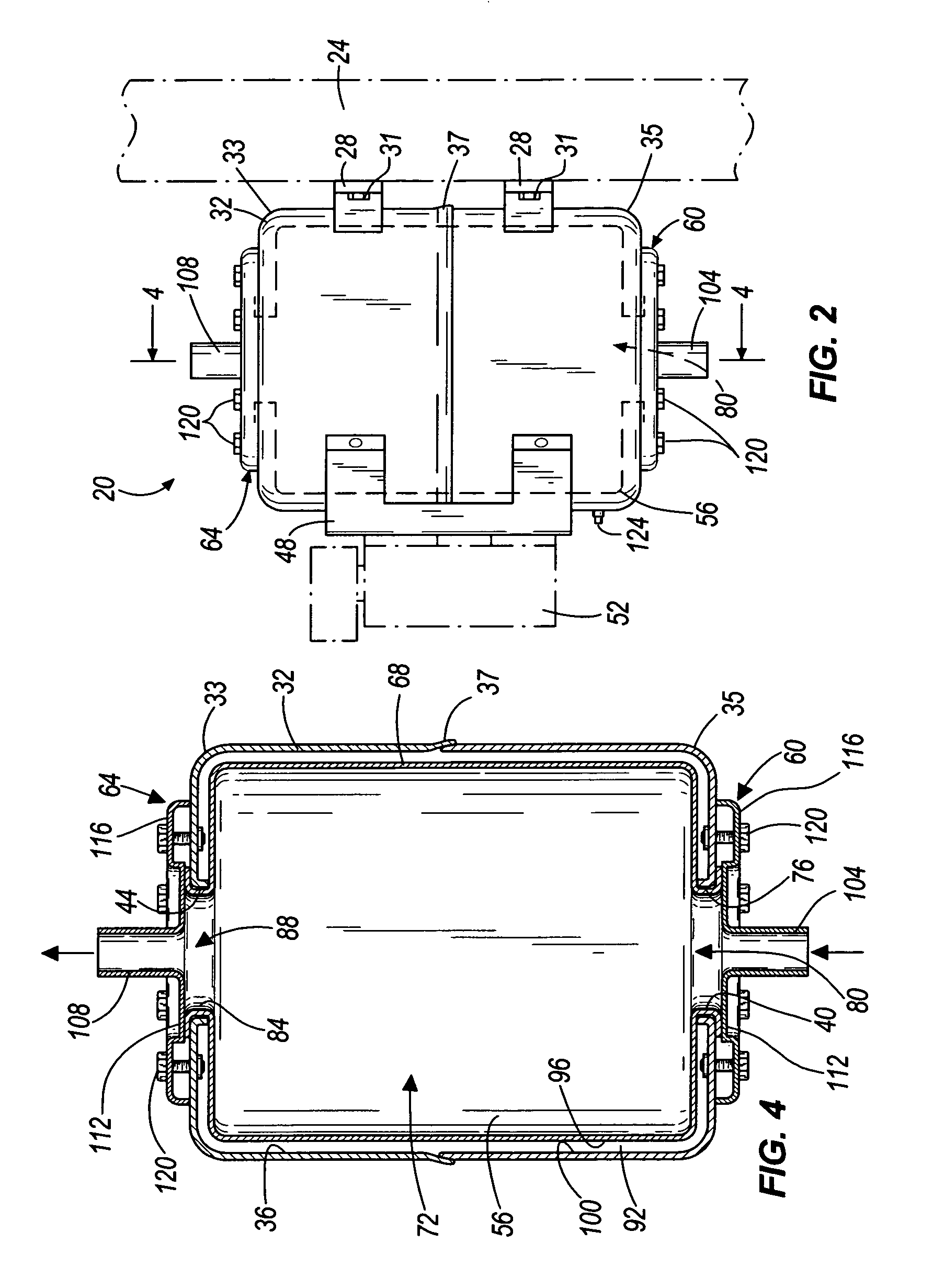
[0014]FIG. 1 illustrates an accumulator tank assembly 20 according to an embodiment of the present invention. The accumulator tank assembly 20 can include an accumulator tank 32 and a flexible bladder 56, both of which are described in greater detail below.

[0015]The accumulator tank assembly 20 can be installed in any fluid supply system (not shown), such as in a water supply system for equipment drawing water in a restaurant, factory, office, residential building, and the like. In other embodiments, the accumulator tank assembly 20 can be installed in systems supplying any other type of fluid.

[0016]The accumulator tank assembly 20 can be oriented in any manner desired, such as in a substantially vertical orientation as shown in FIG. 1 or in a horizontal or angled orientation. In the illustrated embodiment of FIGS. 1–4, the accumulator tank assembly 20 is coupled to a wall or other vertical structure 24. The accumulator tank assembly 20 can be mounted to any structure desired (e.g.,...


PUM


Abstract

Some embodiments of the present invention provide an accumulator tank assembly and method in which a flexible bladder is received within an accumulator tank. The accumulator tank and the flexible bladder can each have an inlet aperture through which fluid is received within the accumulator tank assembly and an outlet aperture through which fluid exits the accumulator tank assembly. In some embodiments, inlet and outlet flanges positioned adjacent the inlet and outlet apertures of the accumulator tank are used to couple the flexible bladder to internal or external surfaces of the accumulator tank, thereby creating fluid tight seals between the flexible bladder and the accumulator tank.

Description

BACKGROUND OF THE INVENTION[0001]Fluid supply systems in industrial, residential, and commercial environments often include one or more accumulator tanks for insuring that the flow rate and pressure of fluid supplied to various locations is substantially steady. Some accumulator tanks contain a reservoir of fluid that can be supplied to the system at peak demand times in order to maintain a substantially steady fluid flow rate and pressure. At times of lower demand, the fluid supply system can replenish such accumulator tanks with fluid.[0002]Accumulator tanks typically include a rigid outer shell having a single aperture through which fluid can flow to and from the fluid supply system. Accumulator tanks also typically include a flexible bladder made from a porous material, such as butyl rubber, positioned within the rigid outer shell. This flexible bladder also has a single aperture aligned with the aperture in the shell and through which fluid can flow to and from the fluid supply...

Claims


Application Information

Patent Timeline
IPC IPC(8): F16L55/04
CPCF15B1/021F15B1/04F15B2201/20F15B2201/605F15B2201/413F15B2201/60F15B2201/3152
Inventor SAVELIEV, MICHAELJERSEY, STEVEN T.
Owner SHURFLO
Why Eureka
Try Eureka