Percutaneous technique and implant for expanding the spinal canal

a percutaneous technique and spinal canal technology, applied in the field of spinal surgery, can solve the problems of scar tissue around the nerves, recurrent pain, back muscle dysfunction and pain, etc., and achieve the effect of relieving pressure on the spinal nerves, reducing scar tissue, and being safe and permanen

Inactive Publication Date: 2007-01-23
DEPUY ACROMED INC +2
View PDF42 Cites 304 Cited by
  • Summary
  • Abstract
  • Description
  • Claims
  • Application Information

AI Technical Summary

Benefits of technology

[0009]The present invention provides a simple, safe, permanent, and minimally invasive method and apparatus for treating spinal stenosis by expanding the spinal canal area to provide additional space for the spinal nerves, relieving pressure on the spinal nerves.

Problems solved by technology

Although the spinal laminectomy is often successful in relieving pressure on the nerves of the spinal canal, several problems and disadvantages arise as a result of the laminectomy.
First, the laminectomy removes important sites of back muscle attachment leading to back muscle dysfunction and pain.
Second, the laminectomy exposes the nerve sac causing scar tissue to form around the nerves.
Scar tissue may prevent normal motion of the nerves, leading to recurrent pain.
Third, the laminectomy can destabilize the spine resulting in a forward slippage of one vertebra on another.
Vertebral slippage can cause recurrent pain and deformity.
Fourth, the laminectomy requires a large surgical exposure and significant blood loss, making the laminectomy dangerous for older patients.
Finally, spinal stenosis can recur following the laminectomy, requiring risky revision surgery.
Multiple laminotomies, however, also suffer from problems and disadvantages.
Laminotomies may not adequately relieve nerve compression and the pain may continue.
Laminotomies are more difficult to correctly perform than the laminectomy.
Laminotomies expose the nerves and may cause nerve scaring.
Patients receiving multiple laminotomies also often have recurrent spinal stenosis requiring risky revision surgery.

Method used


Image

  • Percutaneous technique and implant for expanding the spinal canal
  • Percutaneous technique and implant for expanding the spinal canal
  • Percutaneous technique and implant for expanding the spinal canal

Examples


Embodiment Construction

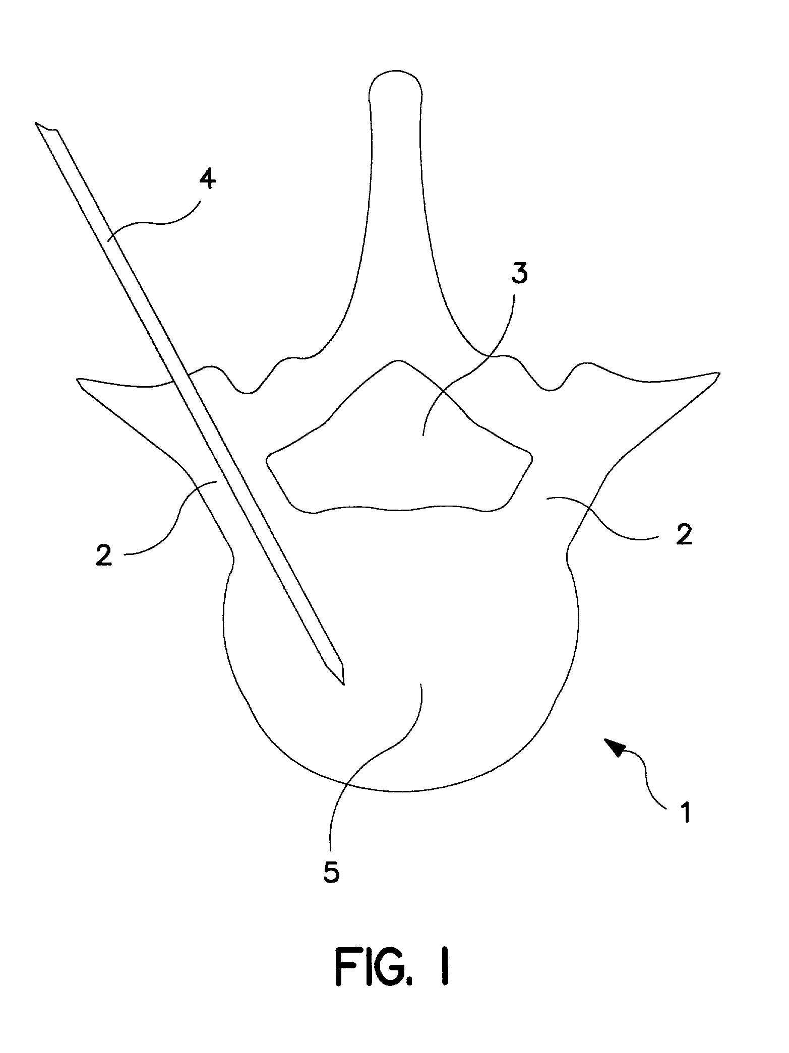
[0052]Referring now to the drawings, where like numeral indicate like elements, there is shown in FIG. 1 a cross section of a vertebra 1 having a vertebral body 5, spinal canal 3 and pedicles 2. Also shown is a guide wire 4 inserted into a central portion of the left pedicle 2 to enter the vertebral body 5.

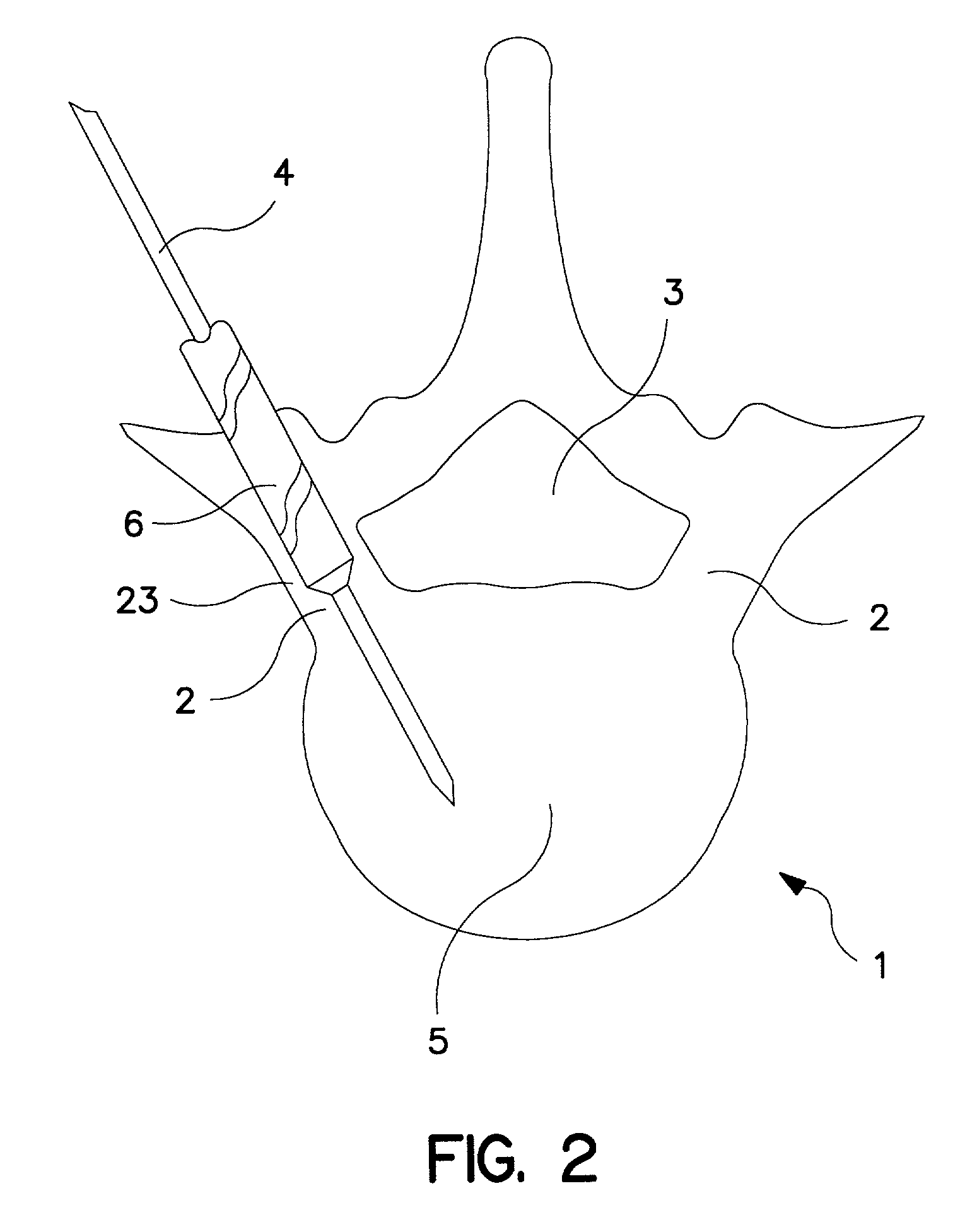
[0053]FIG. 2 illustrates the cross section of the vertebra 1 of FIG. 1, showing a cannulated drill 6 passing over the guide wire 4, drilling a passage in the central portion of the left pedicle 2 but leaving intact outer wall 23 of the left pedicle 2.

[0054]FIG. 3 illustrates the cross section of the vertebra 1 of FIG. 1 following completion of the drilling procedure of FIG. 2, showing a passage 7, or hollow tunnel, spanning the central portion of the left pedicle 2, leaving intact an outer bony wall 23 of the left pedicle 2.

[0055]FIG. 4 illustrates the cross section of the vertebra 1 of FIG. 1 with a side-cutting instrument 8 within the passage 7 of the left pedicle 2. The side-cu...


PUM


Abstract

The present invention expands a spinal canal by drilling a cylindrical passage in each pedicle of a vertebra, making a circumferential pedicle cut (osteotomy) through each pedicle from within the passage, separating each pedicle cut by inserting an implant into the passage which distracts the pedicle cut to expand the spinal canal, and securing each pedicle cut, allowing the vertebra to heal with the spinal canal expanded. The implant includes an outer sleeve, an inner bolt, and expandable flanges. The outer sleeve includes an upper portion and a lower portion, with the expandable flanges connected to the lower portion and housed within the upper portion. Rotation of the inner bolt causes the upper and lower portions of the outer sleeve to separate, causing the pedicle cut to widen and the expandable flanges to radially extend into and stabilize the widened pedicle cut to effectuate expansion of the spinal canal.

Description

RELATED INVENTIONS[0001]This application is a continuation-in-part (CIP) of U.S. Ser. No. 09 / 659,180, filed Sep. 11, 2000 (now U.S. Pat. No. 6,358,254), entitled “A Method and Implant for Expanding a Spinal Canal,” which is hereby incorporated in its entirety by this reference.FIELD OF THE INVENTION[0002]The present invention relates generally to spinal surgery, and more particularly to a method and apparatus for expanding a spinal canal to relieve pressure on spinal nerves.BACKGROUND OF THE INVENTION[0003]Spinal Stenosis, or narrowing of the spinal canal, inflicts millions of people with back and leg pain due to compression of spinal nerves. Severe spinal stenosis often leads to surgery in an effort to relieve compressed nerves and lessen back and leg pain. Spinal laminectomy is the traditional operation performed to treat spinal stenosis. In the spinal laminectomy, posterior aspects of the spinal column are removed to “un-roof” the spinal canal to relieve the pressure on the nerve...

Claims


Application Information

Patent Timeline
Patent Type & Authority Patents(United States)
IPC IPC(8): A61B17/70A61B17/56A61B17/14A61B17/16A61B17/22A61B17/66A61B17/80A61B17/86A61F2/44
CPCA61B17/14A61B17/1617A61B17/1671A61B17/8685A61B17/7071A61B17/1631A61B17/1637A61B2019/307A61B17/8004A61B2017/22038A61B2017/143A61B2017/145A61B2090/037A61B17/149A61B17/70
Inventor ANDERSON, D. GREG
Owner DEPUY ACROMED INC
Why Eureka
Try Eureka