Central circulation completion system

a technology of completion system and completion system, which is applied in the direction of sealing/packing, drilling pipes, and wellbore/well accessories, etc., can solve the problem of no longer being able to circulate fluids in the well

Inactive Publication Date: 2006-03-21
FMC TECH INC
View PDF11 Cites 40 Cited by
  • Summary
  • Abstract
  • Description
  • Claims
  • Application Information

AI Technical Summary

Problems solved by technology

In this circumstance, it is no longer possible to circulate fluids in the well via the annulus and the central tubing string suspended from the tubing hanger performs the function that the annulus traditionally performs.

Method used


Image

  • Central circulation completion system
  • Central circulation completion system
  • Central circulation completion system

Examples


Embodiment Construction

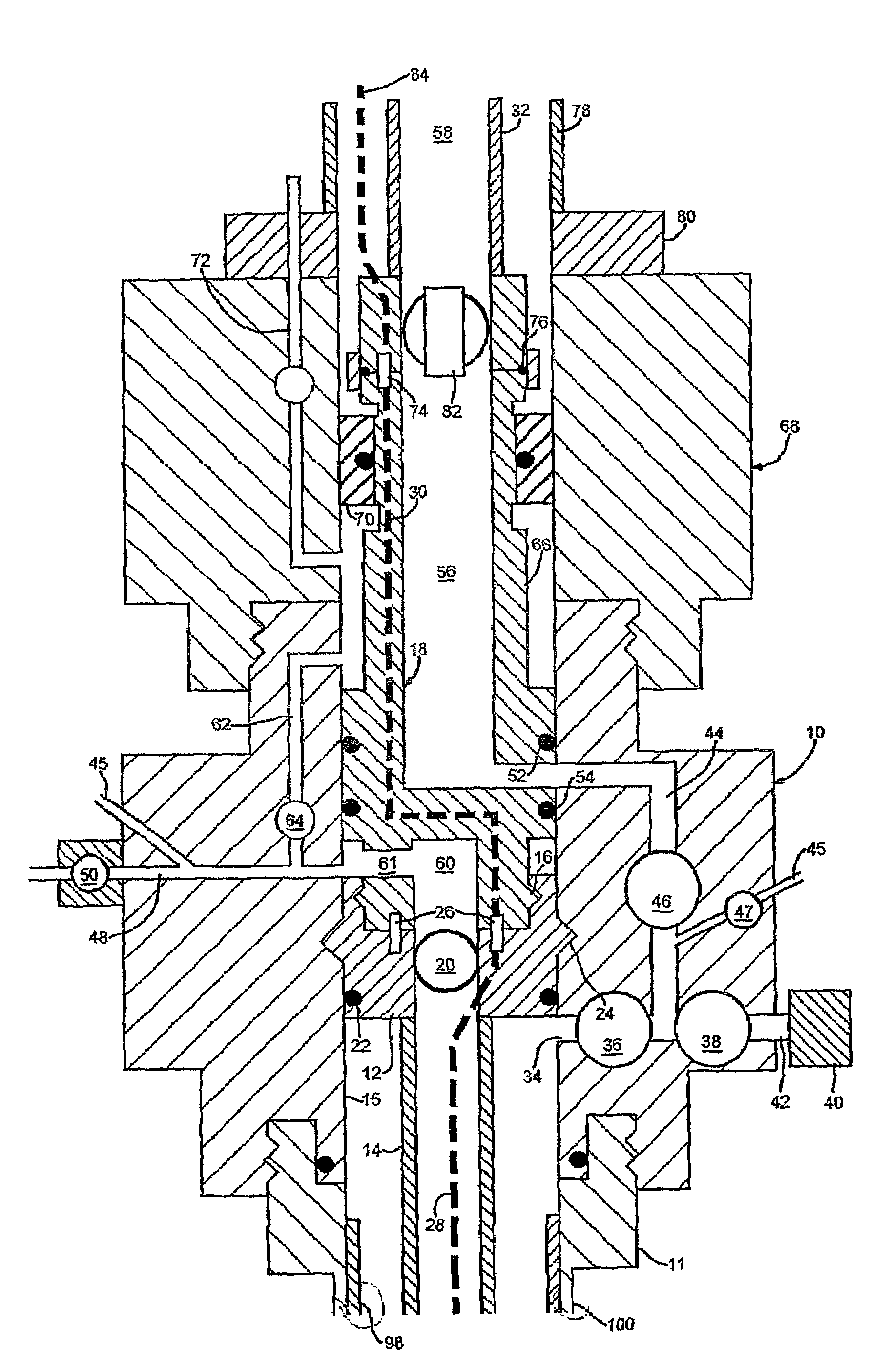
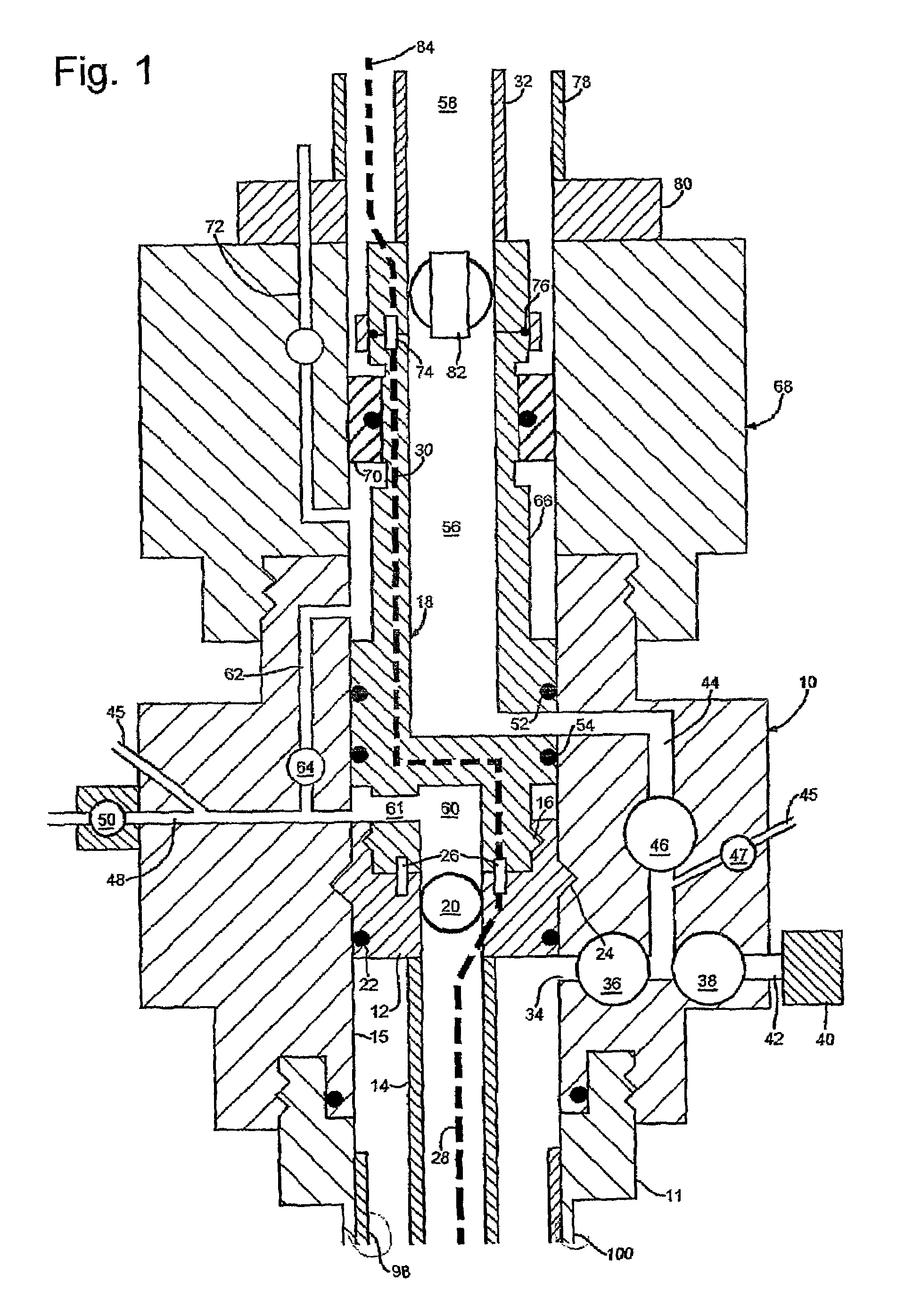
[0025]The preferred completion system includes a subsea christmas tree configuration that will allow the installation of a centrally located service conduit. The preferred well, construction also comprises the following components that are typically used in completions and accordingly the subsea tree design provides the appropriate interfacing equipment:[0026]SCSSV or functional equivalent[0027]Downhole chemical injection[0028]Gas lift mandrels[0029]Downhole instrumentation, e.g. pressure and temperature gauges

[0030]The central service conduit provided by a central coiled tubing string is preferably replaceable with minimum impact on the installed second or outer production tubing and subsea christmas tree equipment. The outer tubing string is terminated at the wellhead housing (either with or without a tubing hanger) and the tree seals to the wellhead housing with a seal stab.

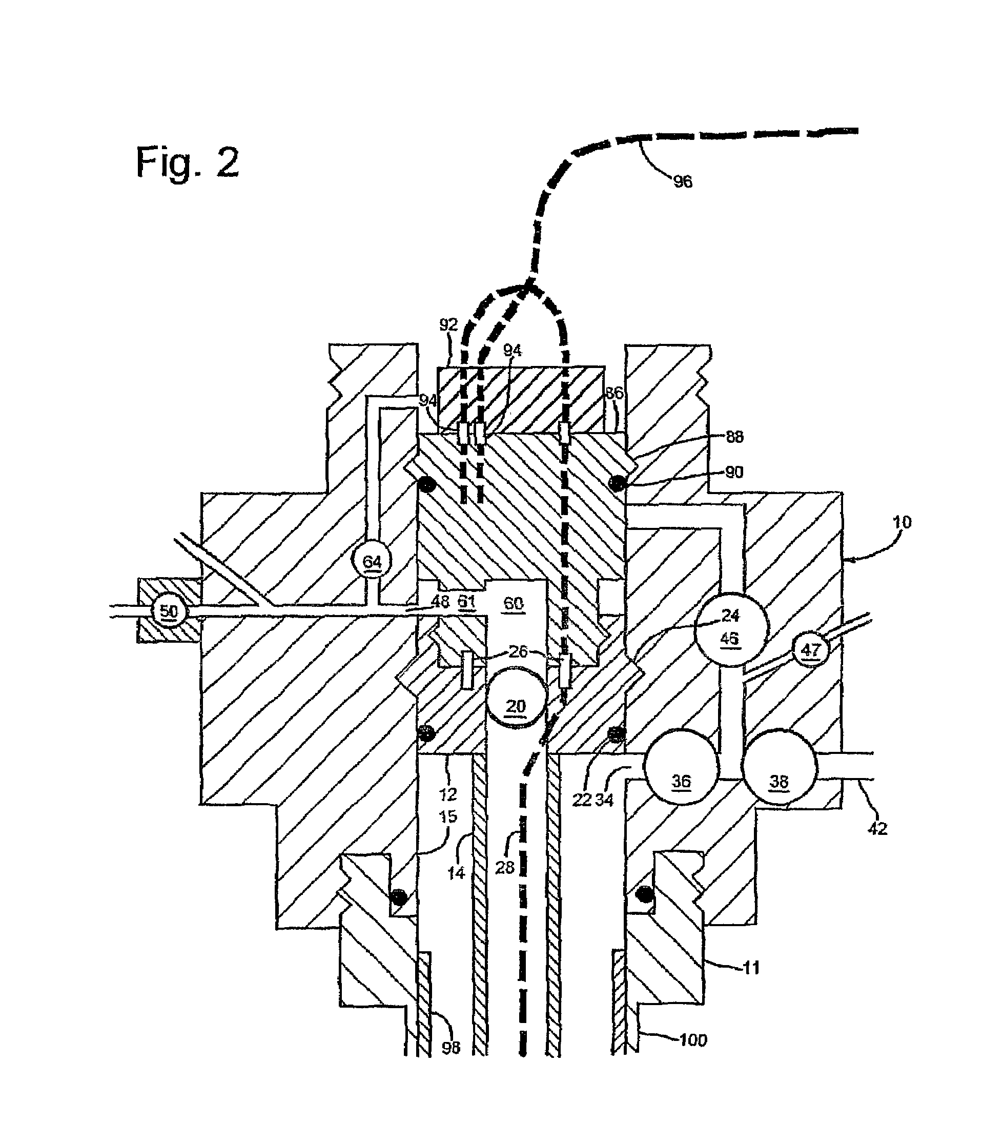
[0031]Referring to FIG. 1, coiled tubing 14 is suspended from a coiled tubing hanger 12 in a horizontal chr...


PUM


Abstract

A completion system comprises a christmas tree (10) mounted on a wellhead housing (11), a tubing hanger (12) landed in the tree or wellhead housing, the wellhead housing (11) being mounted on a casing string (100) and a tubing string (14) being suspended from the tubing hanger within the casing string; wherein, in use, the annulus defined between the tubing (14) and the casing (100) serves as a production bore. A second tubing string (98) is expanded into sealing engagement with the casing string (100) over at least a portion of their lengths. The annulus normally used to provide well service functions is thus eliminated. Well servicing is instead provided via the tubing string (14), which may be coiled tubing.

Description

INVENTION BACKGROUND[0001]Traditionally, a subsea christmas tree provides pressure control of a well completion system that comprises a centrally located well bore and a surrounding annulus conduit. The centrally located well bore is typically used for the extraction of reservoir hydrocarbons and is referred to as the production bore. The annulus conduit is typically used to service the well, for example allowing the circulation of fluids during well start up and shut down. During the production phase of the well, the annulus is often redundant and is monitored for pressure build up indicating a possible production tubing or packer leak from the production bore. Some wells employ the annulus for gas lift. Gas is pumped down the annulus and enters the production bore at specific locations thereby reducing the density and viscosity of the produced fluids. Electrical, optical and hydraulic service lines are also typically routed through the annulus for powering and control of downhole ...

Claims


Application Information

Patent Timeline
Patent Type & Authority Patents(United States)
IPC IPC(8): E21B33/03E21B33/038E21B29/08E21B33/035E21B33/04E21B33/047E21B34/02E21B34/04E21B43/10
CPCE21B29/08E21B33/03E21B33/035E21B43/103E21B33/047E21B34/02E21B34/04E21B33/04E21B33/0353E21B33/043
Inventor COLLIE, GRAEME JOHNHUTCHISON, DAVID RAMSAYKENT, RICHARD
Owner FMC TECH INC
Why Eureka
Try Eureka