Method of completing poorly consolidated formations

a technology of poorly consolidated formations and wells, applied in the direction of fluid removal, borehole/well accessories, chemistry apparatus and processes, etc., can solve the problems of poor results, gravel and screen may be plugged by scale or eroded, and high undesirable sand production

Active Publication Date: 2006-03-21
SCHLUMBERGER TECH CORP
View PDF29 Cites 90 Cited by
  • Summary
  • Abstract
  • Description
  • Claims
  • Application Information

AI Technical Summary

Benefits of technology

[0014]Another aspect of the present invention is a method for completing in a subterranean formation an unconsolidated interval susceptible to produce particulates such as sand, including the step of consolidating said interval by injecting into said interval an aqueous solution of a mixture of colloidal particles, of a pH modifier and / or an ionic-strength modifier to form a hard gel that holds the particulates together, and of a diverting agent to promote uniform flowrates of the aqueous solution through regions of the interval with dissimilar permeabilities and then, the step of hydraulically fracturing the consolidated interval.

Problems solved by technology

Such a production of sand is highly undesirable since it erodes surface and subterranean equipment, requires a removal process before the hydrocarbon can be process and eventually, counteracts the suitable effects of stimulation techniques such as acid stimulation.
However, this technique is relatively onerous and with time, the gravel and the screen may be plugged by scale or eroded by the sand.
Further, poor results are achieved with heterogeneous formations consisting for example of layers having different permeabilities.
Resin-based consolidation systems are known to be very complicated to apply, for instance requiring up to five treatment stages and often raise environmental issues.
Though some successes have been obtained with most of the above-mentioned techniques, none of them has achieved large commercial acceptance, in particular in view of the technical and cost limitations.

Method used


Image

  • Method of completing poorly consolidated formations
  • Method of completing poorly consolidated formations
  • Method of completing poorly consolidated formations

Examples


example 1

Selection of Suspension

[0037]Ten commercial suspensions of aqueous colloidal silica were tested. Some characteristics of the suspensions are reported in Table 1 below, including the charge (N: negative, P: positive), the average particles size, the silica content, the specific surface and the pH. The suspensions were gelled either by addition of salt (2 ml of NaCI 4M added to 14 ml of colloidal suspension); see results in Table 2, or by addition of hydrochloric acid (aqueous solution at 15 wt %) to 15 ml of colloidal suspension; see results in Table 3. After 2 days at 66° C., the gel resistance was estimated with a spatula, by exerting a low stress (gel resistance 1) or a high stress (gel resistance 5). A value ranging between 1 and 5 was attributed depending on the gel distance (1 for very low gel strength, 5 for high gel strength).

[0038]

TABLE 1Av. Part.#ChargeSize (nm)Silica (wt %)Ssp (m2 / g)pH 1N73034510 2N12302208.9 3N12402209.7 4N22501409 5N415Unknown11 6N10050Unknown9 7N4050 80...

example 2

Optimum pH

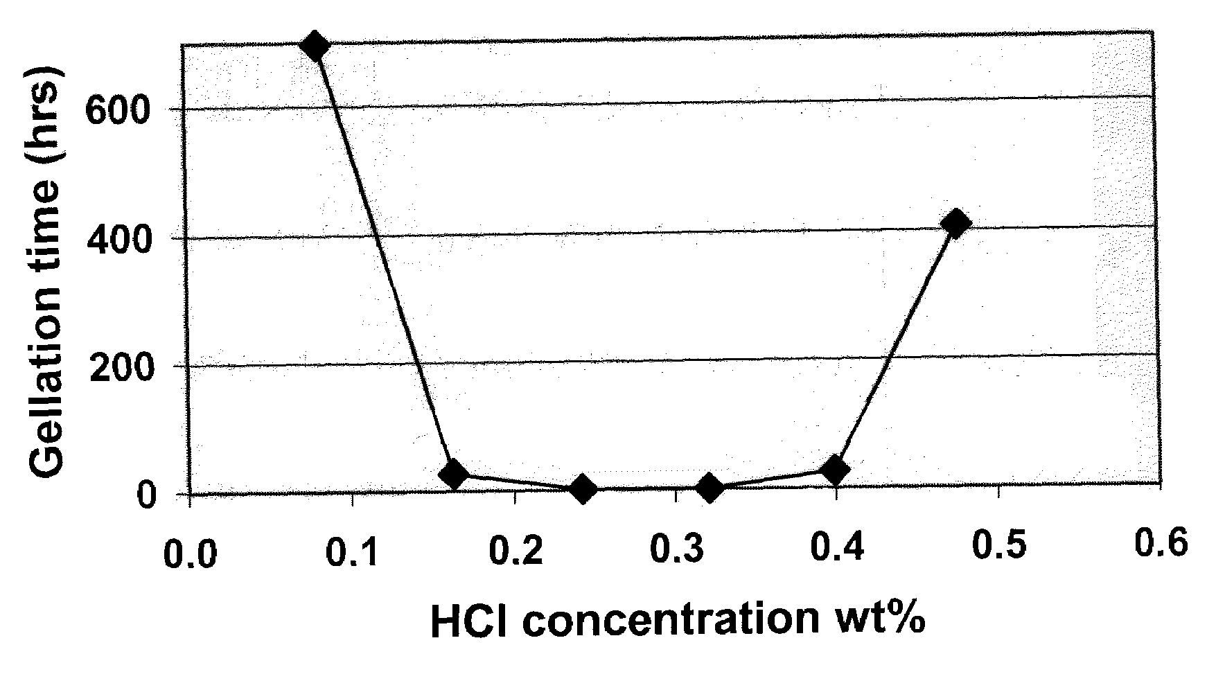
[0042]The suspension #3 of Example 1 was selected. To 15ml of suspension, various amounts of hydrochloric acid were added. The relation between the total HCl concentration in the suspension and the gelling time (in hours) at room temperature is depicted FIG. 1. The shortest gelling time was obtained with an acid concentration of 0.32 wt %, corresponding to a pH between about 6 and about 7.

[0043]When the same test was repeated with the suspension #1 of Example 1, it was found that the shortest gelling time was obtained with a pH between about 5 and about 6. This shows that when acid is used to cause gelation, the concentration should preferably be adjusted for the pH of the suspension to be just slightly acidic (pH between about 5 and about 7) to obtain the shortest gelation time.

example 3

Injection Tests

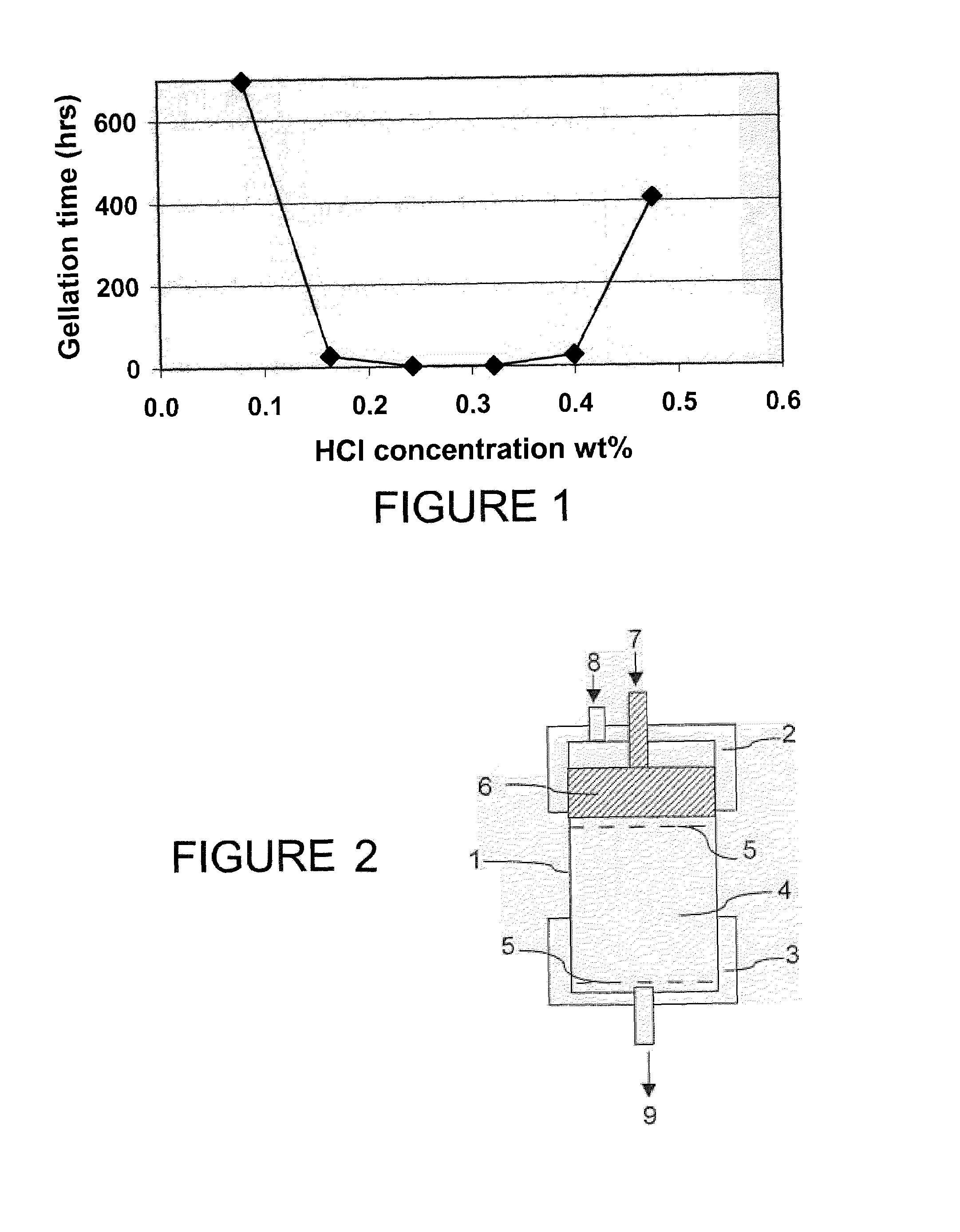
[0044]FIG. 2 is a schematic diagram of the device used to evaluate the injectivity of colloidal silica into sand packs of various permeabilities. This device includes a tubular cell 1, closed at one extremity with a top cap 2 and with a lower cap 3 at the other extremity. A sand pack 4 is placed into the cell 1, between two mesh screens 5. A piston 6 includes a fluid inlet 7 for the injection of the treatment and pretreatment fluids. The cell is further linked to a gas source 8 such as nitrogen that allows to pack the sand by pushing on the piston. The lower cap comprises a fluid outlet 9 to collect the fluids that have traveled through the sand pack 4.

[0045]A 750 mD sand pack was preflushed with a 2 wt % KCI brine before the injection of the colloidal silica suspension #1 of Example 1, and a concentration of hydrochloric acid of about 0.45 wt % (pH between 6 and 7). The injection pressure was only 6 psi at ambient temperature. The cell was left in oven for a night at...


PUM

PropertyMeasurementUnit
diameteraaaaaaaaaa
diameteraaaaaaaaaa
diameteraaaaaaaaaa

Abstract

It is proposed a method for completing an unconsolidated interval, including particulates, in a subterranean formation, including a consolidation steps. The consolidation step is performed by injection of an aqueous solution of colloidal particles with a pH modifier and / or an ionic-strength modifier. A hard gel is formed that holds the particulates together. The consolidation is followed by hydraulic fracturing. Diversion towards area of less permeability may be enhanced by the use of micrometric particles.

Description

BACKGROUND OF INVENTION[0001]This invention relates generally to completion methods of subterranean wells and more particularly to methods and means for completing poorly consolidated formations whereby sand production is eliminated or reduced.[0002]Hydrocarbon fluids such as oil and natural gas are obtained from a subterranean geologic formation, i.e., a reservoir, by drilling a well that penetrates the hydrocarbon-bearing formation. Once a wellbore has been drilled, the well must be completed; a completion involves the design, selection, and installation of equipment and materials in or around the wellbore for conveying, pumping, or controlling the production or injection of fluids. After the well has been completed, production of oil and gas can begin.[0003]Hydraulic fracturing is a primary tool for improving well productivity by placing or extending channels from the wellbore to the reservoir. This operation is essentially performed by hydraulically injecting a fracturing fluid ...

Claims


Application Information

Patent Timeline
Patent Type & Authority Patents(United States)
IPC IPC(8): E21B33/138E21B43/26C09K8/504E21B43/02
CPCC09K8/5045E21B43/261E21B43/025C09K8/572
Inventor DANICAN, SAMUELSALAMAT, GOLCHEHREHPENA, ALEJANDRONELSON, ERIK
Owner SCHLUMBERGER TECH CORP
Why Eureka
Try Eureka