
Brake pad clearance sensor

Inactive Publication Date: 2006-03-21
ARVINMERITOR TECH
View PDF8 Cites 32 Cited by
  • Summary
  • Abstract
  • Description
  • Claims
  • Application Information

AI Technical Summary

Benefits of technology

[0010]Accordingly, the present invention provides an accurate and adaptable method and device for determining clearance between a friction element and a rotating member of a brake assembly.

Problems solved by technology

Disadvantageously, mechanical switches provide only limited accuracy and dependability.
Further, mechanical switches require specific actuation features on brake member components, and are difficult to adapt to different actuator assemblies.

Method used


Image

  • Brake pad clearance sensor
  • Brake pad clearance sensor
  • Brake pad clearance sensor

Examples


Embodiment Construction

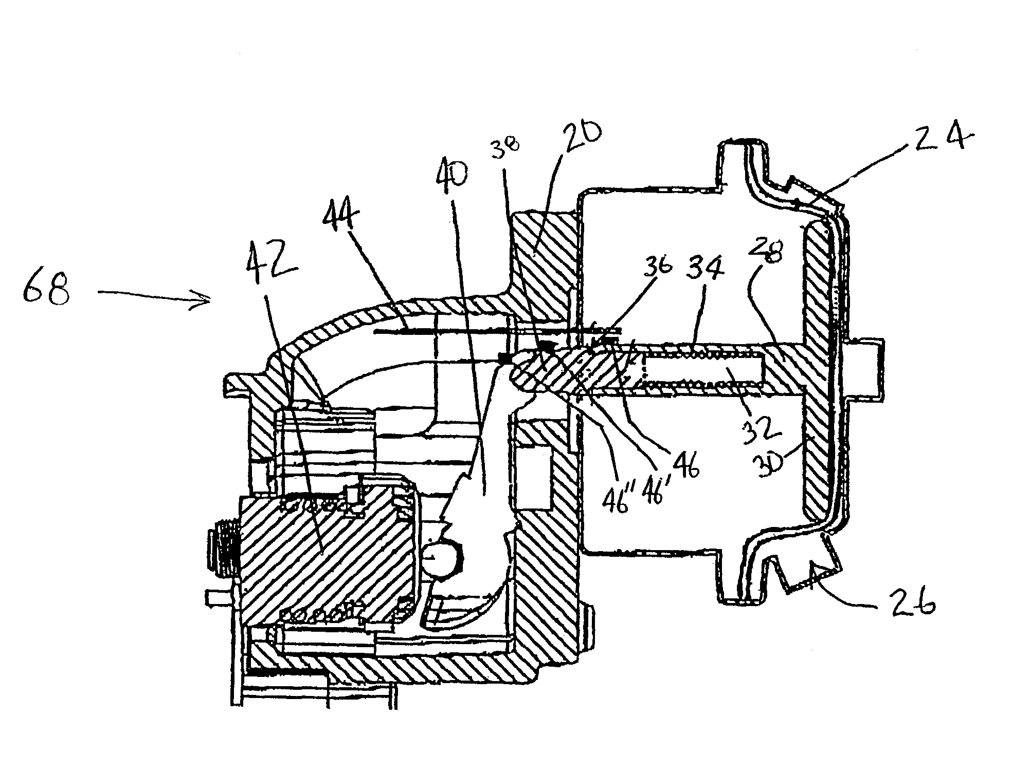
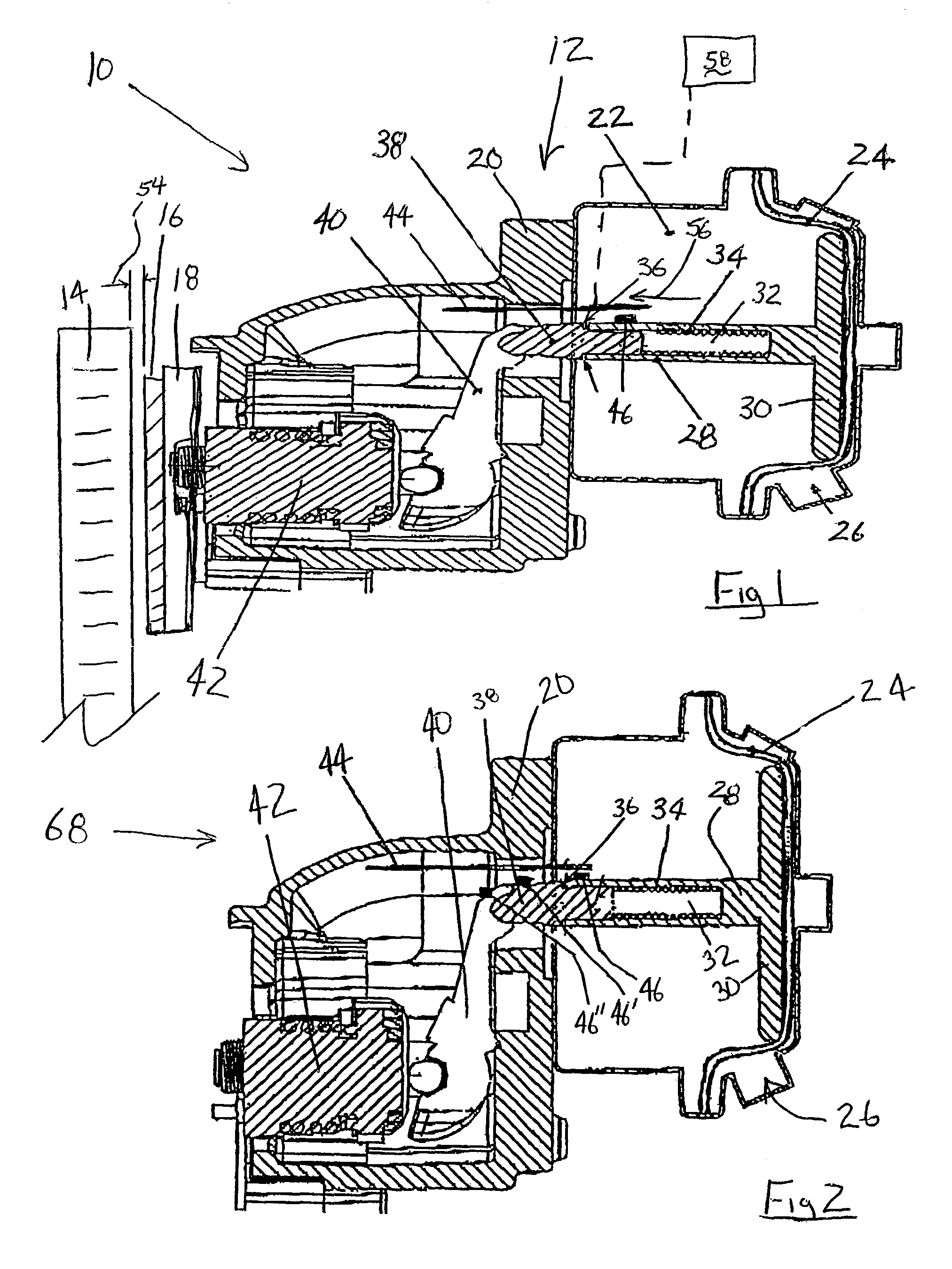
[0017]Referring to FIG. 1, a brake assembly 10 includes an actuator 12 for moving a brake pad 18 into frictional engagement with a rotor 14. Friction material 16 mounted to the brake pad 18 selectively contacts the rotor 14. Clearance 54 between the friction material 16 and the rotor 14 changes during use due to normal wear.

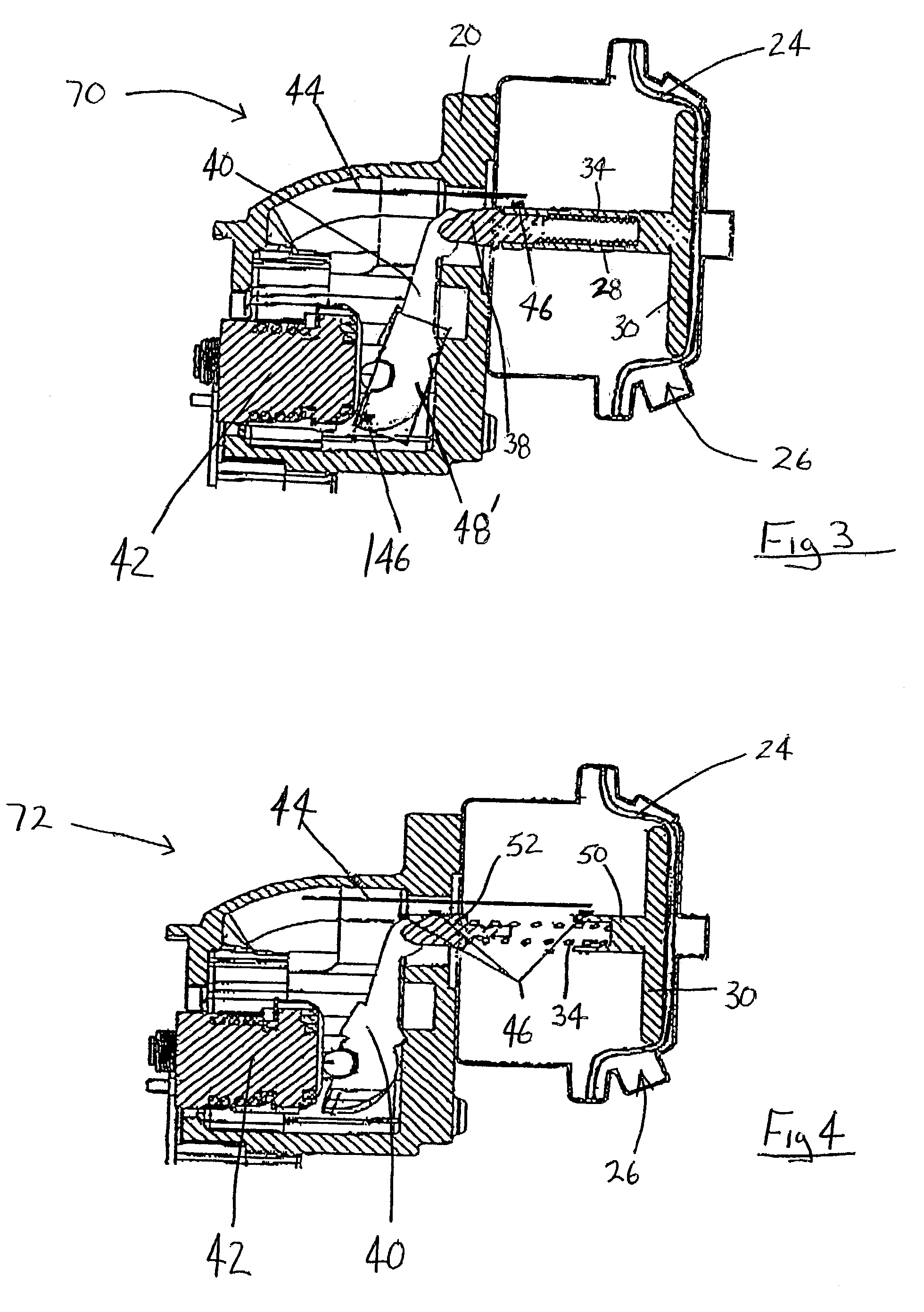
[0018]A transceiver antenna 44 sends signals of a predetermined frequency to a sensor 46. Preferably, the sensor 46 is an inductive resonance device, such as a transponder that transmits a signal in response to a signal received. Transmissions from such transponders are powered by the received signal. However, other passive or active sensors known to a worker skilled in the art are within the contemplation of this invention. Inductive resonance devices require no external electrical connection or power source and therefore are adaptable to brake actuators of many different configurations.

[0019]The sensor 46 is disposed on a push rod 28. In response to signals tra...


PUM


Abstract

A brake actuator assembly includes a sensor mounted to a push rod which is in communication with a transceiver antenna. The sensor provides positional information of the push rod relative to the antenna. A clearance between a friction element and a rotating brake member is determined based on displacement of the push rod and known mechanical relationships within the brake actuator.

Description

BACKGROUND OF THE INVENTION[0001]This invention generally relates to a brake actuator assembly, and specifically to a brake actuator assembly including a sensor for monitoring clearance between a friction element and a rotating member.[0002]Conventional brake assemblies include an actuator for moving a friction element into contact with a rotating member. Typically, an actuator drives the friction element from a home position into contact with the rotating member. Wear of the friction element increases the distance that the friction element must move to contact the rotating member. The increased distance is typically accommodated by mechanical devices that compensate for friction element wear by adjusting a home position closer to the rotating member.[0003]A known brake actuator includes a push rod movable in response to changes in air pressure within an air chamber. The push rod includes a hollow inner cavity for a biasing spring. Movement of the push rod is transmitted through the...

Claims


Application Information

Patent Timeline
IPC IPC(8): F16D66/00
CPCF16D66/00F16D2066/003
Inventor MORRIS, ROYSTON LEONARDNORMAN, MARK ANTHONYTAYLOR, MARTIN PORSCLARKE, LESTERTHOMAS, JEFFREY CLIVEKRAMER, DENNIS A.COSTELLO, ROBERT E.SCHOENHALS, JEFFREY ALLENGUENTHER, PAUL C.
Owner ARVINMERITOR TECH
Features
  • Generate Ideas
  • Intellectual Property
  • Life Sciences
  • Materials
  • Tech Scout
  • Unparalleled Data Quality
  • Higher Quality Content
  • 60% Fewer Hallucinations
Learn More