Eureka AIR delivers breakthrough ideas for toughest innovation challenges, trusted by R&D personnel around the world.

Generating a stereoscopic representation

Active Publication Date: 2020-01-30
SIEMENS HEALTHCARE GMBH
View PDF5 Cites 2 Cited by
  • Summary
  • Abstract
  • Description
  • Claims
  • Application Information

AI Technical Summary

Benefits of technology

The present invention provides a method for accurately and efficiently orienting and navigating through an optically opaque part by combining a camera image and acquisition data obtained by a material-penetrating acquisition modality. The depth location of the camera image is fixed at the depth location of the reference point, which serves as a depth reference between the two different images or data sets. This allows for a consistent depth location relationship in the stereoscopic representation, making it easier to navigate through the opaque part. The invention also allows for a 3D recording of the opaque part and the conversion of the 2D camera image in a more realistic manner using the generated 3D model. This reduces the cost and load of the 3D recording and allows for a closer conversion to reality.

Problems solved by technology

When using an optical camera, the problem arises in this case that many materials are optically opaque, and therefore, regions that are arranged behind such an opaque material in the viewing direction of the camera cannot be depicted or at least cannot be depicted without the material being destroyed or damaged locally by the camera.
If, for example, an X-ray device is used instead of the camera, it is then possible to penetrate optically opaque materials, but corresponding X-ray images are often less clear for a respective user and / or less detailed or less revealing due to the inherent characteristics of X-ray technology.
A further significant problem is that often only 2D camera images are recorded or available, and therefore, even if supporting arrows, subsidiary lines, contour lines, or similar are superimposed, no defined or reliable depth information or depth effect is present in corresponding representations.
As a result of this, precise orientation and examination of the respective object is often significantly hampered.

Method used


Image

  • Generating a stereoscopic representation
  • Generating a stereoscopic representation

Examples


Embodiment Construction

[0043]In the exemplary embodiments described below, the described components of the embodiment variants represent in each case individual features to be viewed independently of each other. The individual features also develop the present embodiments independently of each other in each case and are therefore to be considered as part of the present embodiments whether individually or in a combination other than that shown. The described embodiment variants may also be supplemented by further features described above.

[0044]Identical elements, functionally identical elements, or elements corresponding to each other are labeled by the same reference signs in each case in the figures.

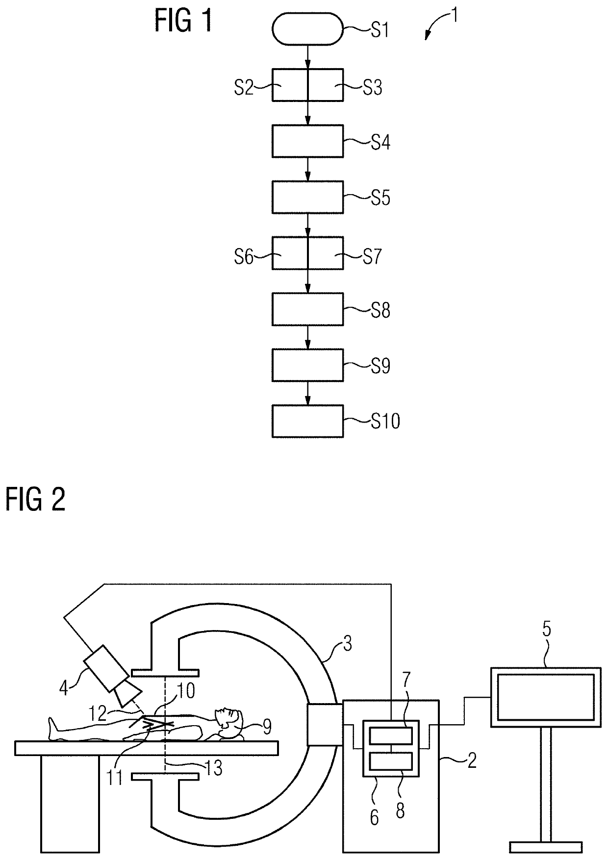
[0045]FIG. 1 shows an exemplary schematic flowchart 1 of one embodiment of a method for generating a stereoscopic representation of a target object. This method is explained in greater detail with reference to the other figures. FIG. 2 shows a schematic representation of one embodiment of an imaging system 2 ...


PUM


Abstract

A camera image is acquired by a camera and a structure that is optically concealed in the camera image is acquired by a material-penetrating acquisition modality. A stereoscopic depth location of a common reference point is then fixed at a predetermined value. The stereoscopic representation is then generated from the camera image, and an overlay image is generated based on the concealed structure. In this case, a depth location of the camera image is fixed at the depth location of the reference point, and, as a function thereof, a depth location of the overlay image is adjusted in relation to the depth location of the reference point, such that in the stereoscopic representation, the overlay image appears realistically in front of and / or behind an optically opaque part in the recording direction of the camera image.

Description

[0001]This application claims the benefit of EP 18186096.6, filed on Jul. 27, 2018, which is hereby incorporated by reference in its entirety.BACKGROUND[0002]The present embodiments relate to generating a stereoscopic representation of a target object.[0003]All manner of objects are examined and / or manipulated for all variety of purposes in many different application fields. The respective objects are often depicted by a camera in this case, and a corresponding camera image of the object is represented on a display device. This may be advantageous if, for example, an examination region of the object cannot easily be accessed or viewed (e.g., due to limited spatial conditions and / or lighting conditions that are inadequate for direct observation). Even in such situations, the currently available camera technology allows advantageously useful images to be generated. In restricted spatial conditions, a miniaturized endoscopic camera, for example, may be used. It is therefore possible to...

Claims


Application Information

Patent Timeline
IPC IPC(8): H04N5/272G06T17/00H04N13/156H04N13/128G06T7/70G06T7/33
CPCG06T2207/20212G06T2207/30108G06T7/33G06T7/70G06T2207/10116G06T2207/30204H04N5/272G06T2207/30004G06T2207/10088H04N13/128H04N13/156G06T17/00A61B6/5247A61B6/12A61B6/4441A61B6/487A61B1/005A61B1/00098A61B1/018
Inventor ALZAGA, AMILCARREGENSBURGER, ALOIS
Owner SIEMENS HEALTHCARE GMBH
Why Eureka
Eureka Blog
Learn More