Method of and apparatus for generating a representation of an object

Active Publication Date: 2006-12-26
STONECUBE
View PDF1 Cites 10 Cited by
  • Summary
  • Abstract
  • Description
  • Claims
  • Application Information

AI Technical Summary

Benefits of technology

[0011]It is thus possible to provide a computer aided design and visualization software package which models the real world operations that can be applied to a substrate such that the end result is a realistic representation of the actual result which would be achieved by applying those operations in the real world. It is thus possible to give graphic designers the power to visualize the end result of their work prior to committing it to printing or production.
[0015]Advantageously the user can select an environment in which to view the model of the object. The environments, may, for example, include representations of a shop, an office and a room within a house. This list is not exhaustive. Each environment has its own lighting conditions which illuminate the model. Thus, in an extreme example, if a model had a metal foil block finish on part of its surface, then this would be able to reflect parts of the environment towards the viewer. The creation and use of these environments allows the designer to simulate how the object being modeled will look in selected environments representative of real world conditions. This will help demonstrate when certain finishing techniques or contrasting features do or do not give the desired effect.
[0026]It is thus possible to provide a user interface which enables a relatively inexperienced user to select operations that will be applied to chosen areas on a substrate, and to view the effect of a applying these operations in a specified order to the substrate.
[0028]Advantageously the user can alter the position of the model within the environment surrounding the model so that the user can simulate, for example, the effect of rotating the model or moving a viewpoint within the environment. The user may also be able to zoom into or away from the model, move the model or viewpoint sideways relative to each other (pan and scroll) and / or view the model in a different environment.

Problems solved by technology

However in general these packages only model color, and not other surface appearance properties of a printed object such as gloss, haze or relief.
These products generally require expert users and are typically not aimed at graphic designers and printers.

Method used


Image

  • Method of and apparatus for generating a representation of an object
  • Method of and apparatus for generating a representation of an object
  • Method of and apparatus for generating a representation of an object

Examples


Embodiment Construction

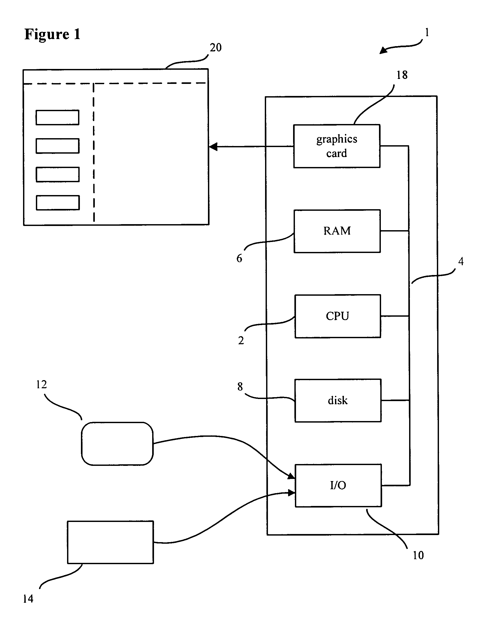
[0040]FIG. 1 schematically illustrates a computer system, generally indicated 1, suitable for performing the present invention. The computer comprises a central processing unit 2 which is connected via a bus 4 to semiconductor random access memory 6, a hard disk 8 (and its associated controller), an input / output controller 10 which is in turn connected to user input devices such as a mouse 12 and a keyboard 14. The central processing unit is also connected via the bus 4 to a graphics card 18 which in turn drives a display device 20 which typically will be of a well known display technology such as an liquid crystal display or a cathode ray tube display. The computer 1 may also have connections to a local area network and also to a scanner or a camera for the input of graphic images. For the purposes of the description, it will be assumed that this functionality is provided within the input output controller 10.

[0041]The disc 8 provides bulk store of software, such as the computer op...


PUM


Abstract

A computer implemented method for examining the appearance of a printed object within a virtual environment is provided. A graphic designer or other user defines the shape and substrate of the object and the sequence and spatial extent of surface processing operations that are to be applied to the object. The method models the result of applying each surface processing operation in sequence.

Description

FIELD OF THE INVENTION[0001]The present invention relates to the computer aided design and visualization of the surface of an object, and in particular to an object which has been subject to a series of surface processing operations, such as printing, coating or decoration, which effect the surface appearance of the object.BACKGROUND OF THE INVENTION[0002]Several computer related products now exist for the design of objects, and which also enable the appearance of the object to be visualized.[0003]Existing 2-dimensional graphic design software includes “Freehand” and “Illustrator” which are drawing packages, “QuarkXpress” and “InDesign” which facilitate page layout and “PaintShop Pro” and “Adobe Photoshop” which are image editors. These products all allow creation of two dimensional images and the modification of those images. They also allow for patterns, shapes, text, colors and graphic objects to be modified and displayed on a flat surface. However in general these packages only ...

Claims


Application Information

Patent Timeline
Patent Type & Authority Patents(United States)
IPC IPC(8): G09G5/00
CPCG06T19/20G06T2219/2012G06T2219/2021
Inventor COULTHARD, MARTIN A.
Owner STONECUBE
Why Eureka
Try Eureka