Dispensing device having a storage chamber, dispensing chamber and a feed regulator there between

a technology of dispensing device and dispensing chamber, which is applied in the direction of instruments, de-stacking articles, computer control, etc., can solve the problems of affecting the dispensing process, the grooved platen has a tendency to damage some medicaments,

Inactive Publication Date: 2006-03-21
PARATA SYST
View PDF28 Cites 174 Cited by
  • Summary
  • Abstract
  • Description
  • Claims
  • Application Information

AI Technical Summary

Benefits of technology

[0012]The present invention is also directed to a method of storing in a bulk storage chamber a volume of medicament, dispensing the medicament from a dispensing chamber, and regulating a rate

Problems solved by technology

The operator must also insure the hopper is not overfilled; otherwise the excess medicament will affect accurate dispensing and could damage the medicament by crushing, grinding or jamming.
How

Method used


Image

  • Dispensing device having a storage chamber, dispensing chamber and a feed regulator there between
  • Dispensing device having a storage chamber, dispensing chamber and a feed regulator there between
  • Dispensing device having a storage chamber, dispensing chamber and a feed regulator there between

Examples


Embodiment Construction

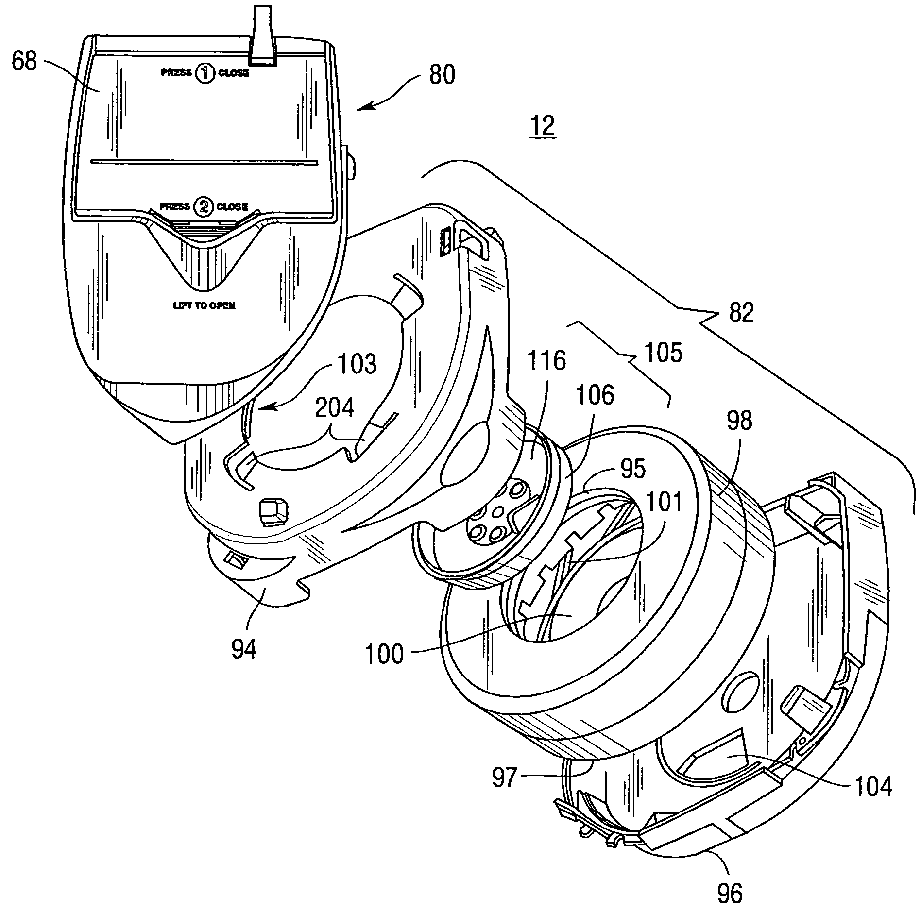
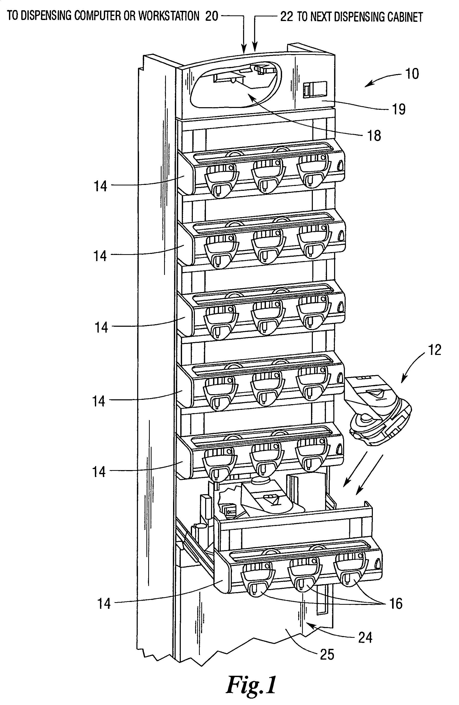
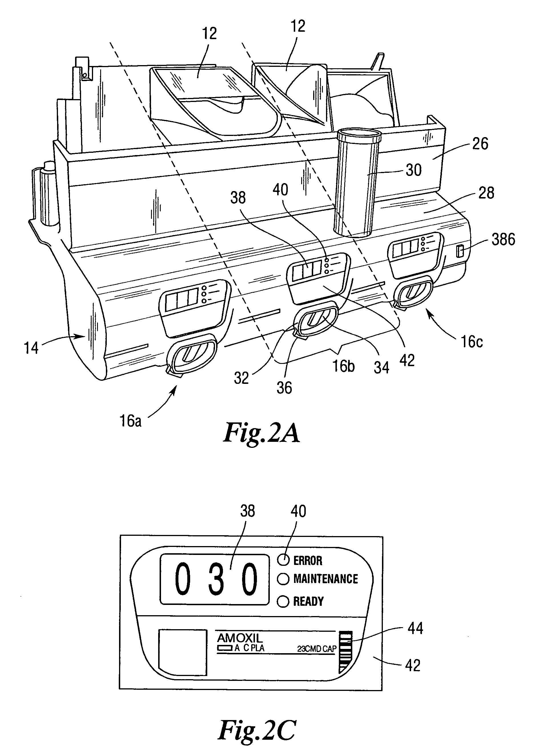
[0068]FIG. 1 illustrates a front view of a medicament dispensing cabinet 10 in which a dispensing device 12 of the present invention may be used. The medicament dispensing cabinet 10 is comprised of a plurality of dispensing drawers 14 each containing three dispensing cells 16. Each dispensing cell 16 is comprised of certain electrical and mechanical components (described below) carried by the drawers 14, which cooperate with a dispensing device 12. Each dispensing cell 16 and dispensing device 12 form one type of dispenser although any type of dispenser, such as a Baker Cell, may be carried by drawers 14. It should be apparent to those skilled in the art that the construction of the medicament dispensing cabinet 10 may be modified to contain fewer or more dispensing drawers 14 to meet different requirements. Also, each dispensing drawer 14 may be constructed to contain fewer than three dispensing cells 16 or more than three dispensing cells 16. Each medicament dispensing cabinet 10...


PUM


Abstract

A drug dispensing device is comprised of an upper hopper having an upper opening for receiving a medicament and a lower opening. A lid covers the upper opening. A lower hopper having an upper opening and a lower opening in a bottom portion thereof is provided. The upper hopper defines a bulk storage chamber and the lower hopper defines a dispensing chamber. A rotatable dispensing disc is positioned in a lower portion of the dispensing chamber for dispensing medicament from the drug dispensing device through the lower opening in the lower hopper. A regulator is situated between the bulk storage chamber and the dispensing chamber for controlling the rate at which medicament moves from the storage chamber to the dispensing chamber. The regulator may take a variety of forms. In one embodiment, the regulator includes a valve for controlling the flow of medicament from the storage chamber to the dispensing chamber. The valve may include a member responsive to the volume of medicament in the dispensing chamber for controlling the position of the valve. The valve and member may include a trap door valve and a float, a butterfly valve and a rotatable arm, a guillotine valve and a movable arm, and a conical plunger and a wing extending from the base of the plunger. In another embodiment, the regulator may include a rotatable member having an opening therein. The rotatable member may include a cylindrical wall having an opening in a portion thereof, a plate having an opening therein, a cup shaped member defining an opening and a pair of rotatable members which together define at least one opening therein. The regulator may be configured such that the rate at which medicament moves from the storage chamber to the dispensing chamber is never zero. Further, agitating members may be provided which extend toward the upper hopper. Methods of operation are also disclosed.

Description

CROSS-REFERENCE TO RELATED APPLICATIONS[0001]This application claims priority from U.S. provisional application Ser. No. 60 / 402,282 filed Aug. 9, 2002 entitled Drug Cartridge and Cabinet for Holding the Same, the entirety of which is hereby incorporated by reference, and U.S. provisional application Ser. No. 60 / 458,160 filed Mar. 27, 2003 entitled Secure Medicament Dispensing Cabinet, Method and System, the entirety of which is hereby incorporated by reference. The present application is related to U.S. application Ser. No. 10 / 637,772 filed herewith and entitled Drug Dispensing Cabinet Having A Drawer Interlink, Counterbalance and Locking System and U.S. application Ser. No. 10 / 637,867 filed herewith and entitled Secure Medicament Dispensing Cabinet, Method and System.BACKGROUND OF THE INVENTION[0002]The present invention is directed broadly to storage and dispensing cartridges, cassettes or cells useful in automated dispensing equipment, particularly for dispensing equipment used f...

Claims


Application Information

Patent Timeline
IPC IPC(8): B23Q7/04A61J7/00G07F5/18G07F5/26G07F11/24G07F11/42G07F11/44G07F11/54G07F11/62
CPCG06F19/3462G07F5/18G07F5/26G07F9/026G07F11/002G07F17/0092G07F11/42G07F11/44G07F11/54G07F11/62G07F11/24G16H20/13G07F9/001G07F9/002G05B15/02G07F11/30
Inventor SHOWS, PAUL RANDALLREMIS, STEVEN J.AKINS, CURTIS R.PARKS, ROBERTKAINTZ, RYANHOLMES, ERIC LAMONTBEALE, MATTHEW STUARTSASS, MATTHEW
Owner PARATA SYST
Why Eureka
Try Eureka