Friction cylinder for a support device

a technology of friction cylinder and support device, which is applied in the direction of machine supports, shock absorbers, building scaffolds, etc., to achieve the effect of facilitating smooth movement of shafts

Inactive Publication Date: 2006-03-21
INNOVATIVE OFFICE PROD INC
View PDF27 Cites 85 Cited by
  • Summary
  • Abstract
  • Description
  • Claims
  • Application Information

AI Technical Summary

Benefits of technology

[0015]In preferred embodiments, the friction bushing will also include a follower bushing disposed within the tubular member at one end of the shaft or rod The follower bushing will secure the rod in a central position within the tubular member to facilitate smooth movement of the shaft. The follower bushing may also act as a stop to prevent the shaft from extending completely free of the tubular member.

Problems solved by technology

When the friction bushing is connected within a support device, it is the frictional resistance to movement of the arm that creates a counterbalance to the weight of at least a portion of the support device and its device.

Method used


Image

  • Friction cylinder for a support device
  • Friction cylinder for a support device
  • Friction cylinder for a support device

Examples


Embodiment Construction

[0029]In describing the preferred embodiments of the subject matter illustrated and to be described with respect to the drawings, specific terminology will be resorted to for the sake of clarity. However, the invention is not intended to be limited to specific terms so selected, and it is to be understood that each specific term includes all technical equivalents which operate in a similar manner to accomplish a similar purpose.

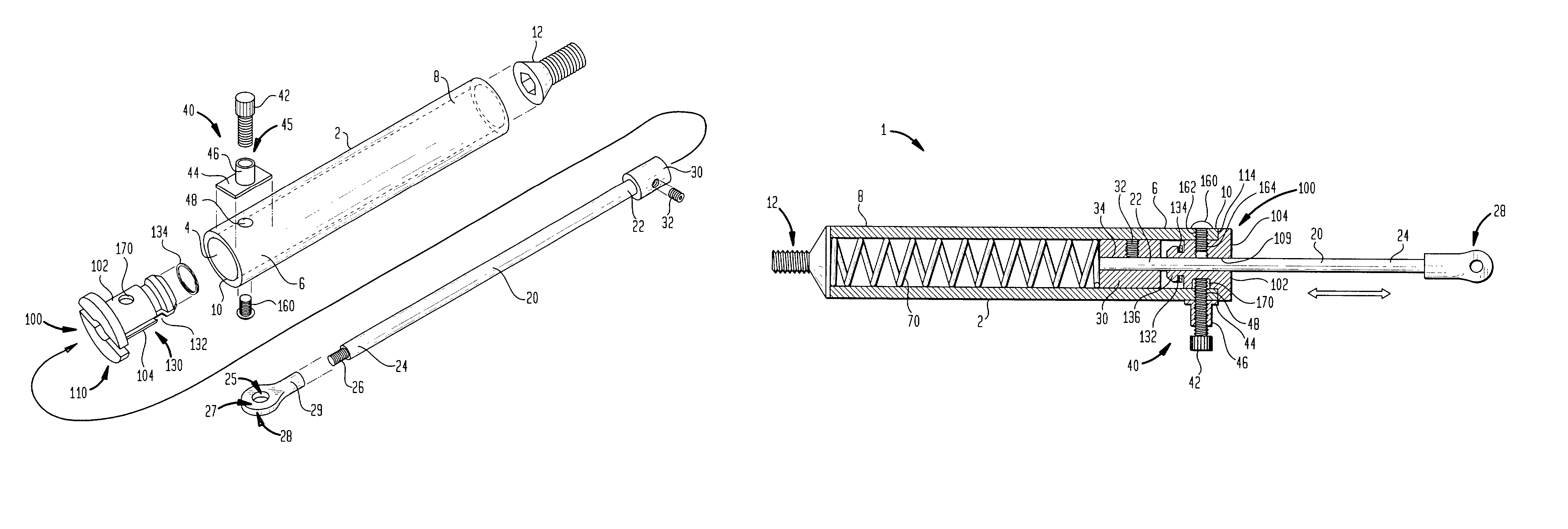
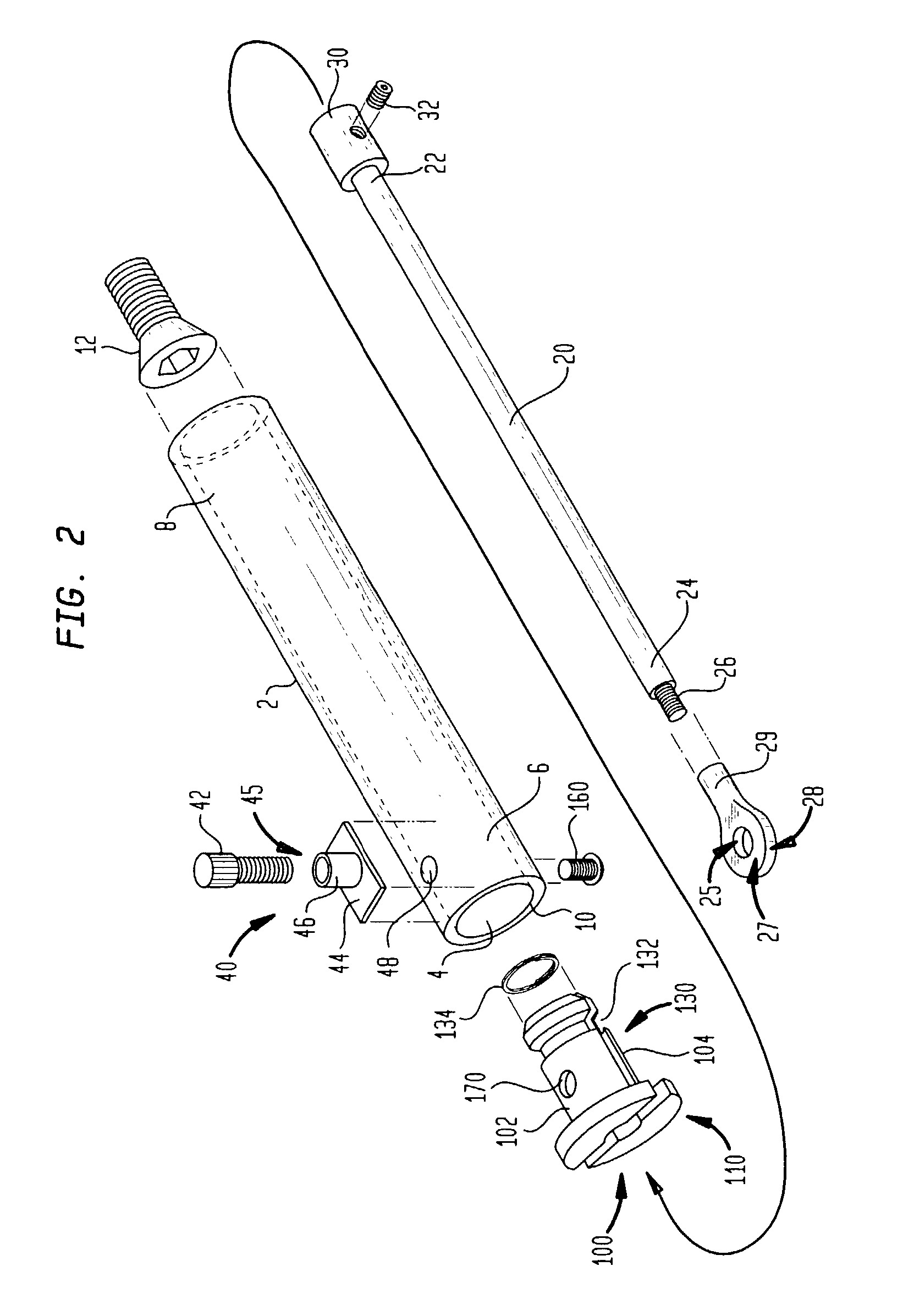
[0030]Referring now to the drawings, wherein like reference numerals represent like elements, there is disclosed in FIG. 2 an exploded view of a friction cylinder of the present invention. The friction cylinder includes an elongated hollow tubular member 2 having an opening 4 defined by the walls of tubular member 2 at a first end 6. A friction bushing 100 is received by opening 4 at the first end 6 of tubular member 2, the friction bushing 100 being adapted to slidably receive a shaft or rod 20. The friction bushing 100 may be tightened about the shaft 20 by...


PUM


Abstract

A positionable support device includes a friction cylinder as a counterbalance in place of conventional gas springs. The support device includes a support arm pivotally secured between two endcaps to allow for vertical movement, the first endcap being mounted to a support structure such as a wall or desktop, the second endcap adapted to engage a mounting element for a device such as an electronic device. A friction cylinder is pivotally attached at one end to the first endcap, and at the other to an outward portion of the support arm. The friction cylinder includes a tubular member open at one end for receiving a friction bushing and a shaft. The friction bushing is secured to the tubular member and has a central passage which allows the shaft to slide through the friction bushing, extending and retracting in relation to the tubular member. The friction bushing is adjusted to apply frictional resistance to movement of the shaft sufficient to support the weight of the support device and the electronic device, thereby allowing the device to be adjusted to a desired vertical position.

Description

BACKGROUND OF THE INVENTION[0001]The invention relates generally to the field of support devices, and more particularly, pertains to support arms for electronic devices, such as a computer monitor, flat screen display, television, or keyboard which are adjustable to a variety of positions and have a counterbalance to support the weight of the electronic device.[0002]Positionable support arms for mounting electronic peripheral devices, such as computer monitors or televisions to, among other things, a wall, column, ceiling, desktop or other support structure are well known in the prior art. Conventional support arms include a rigid elongated arm having a first end pivotally coupled to the support structure for pivoting movement about a generally horizontal first pivot axis and vertically between and upper and lower position. A mounting element is provided for coupling a device to a second end of the rigid arm, which typically provides for pivoting of the device about a second general...

Claims


Application Information

Patent Timeline
Patent Type & Authority Patents(United States)
IPC IPC(8): E04G3/00F16M11/04
CPCF16M11/04F16M11/10F16M11/2014F16M11/24F16M11/2092F16M2200/065F16M2200/044F16M2200/063
Inventor ODDSEN, ODD N.
Owner INNOVATIVE OFFICE PROD INC
Why Eureka
Try Eureka