Fast clutch mechanism for industrial door

a technology for industrial doors and clutches, applied in the direction of interlocking clutches, wing accessories, gearing, etc., can solve the problems of reducing affecting the service life of the shift fork, and consuming a lot of time and energy, and achieves quick clutch operation, good structure, and great convenience.

Inactive Publication Date: 2013-03-26
JIANGXI BAISHENG GATE & DOOR AUTOMATION
View PDF5 Cites 0 Cited by
  • Summary
  • Abstract
  • Description
  • Claims
  • Application Information

AI Technical Summary

Benefits of technology

[0008]For overcoming the above shortcomings of the clutch mechanism, there is provided a fast clutch mechanism which is operative with ease, and has the ability to bring quick disengagement even under urgent situation or highly loaded situation.
[0018]Specifically, the rotation limiting device comprises an axial rib and / or groove formed on an inner wall of the clutch sleeve and a corresponding axial groove and / or rib formed on an external wall of the output shaft. The clutch assembly comprises an axial hole and / or pin disposed on the clutch sleeve and a corresponding axial pin and / or hole disposed on the worm wheel. Each cam shift lever is elongated and has a cross-section of rectangular shape with different length and width, and this facilitates smooth movement of the clutch sleeve during rotation of the cam shift lever. The cross section of the cam shift lever has rounded corners.
[0019]Compared to prior art, the present invention has the following advantages:
[0020]Firstly, pulling of the operating shank by a rope (alternatively, rotation of the chain wheel by pulling a chain) drives the rotation shaft to rotate. The operating shaft takes one end of the rotation shaft as its support point, and thus it works like a lever mechanism (alternatively, a pulley device may be provided on the chain wheel). Consequently, it is possible for the user to perform a quick clutch operation with great convenience on the ground without any risk of climbing on high location necessary to perform clutch operation.
[0021]Secondly, the present invention has a good structure. The clutch sleeve has functions of engagement and disengagement due to transmission among the operating shank, the rotation shaft, the primary bevel gear, the drive gear, the follower gears, and the cam shift lever, especially the transmission between the primary bevel gear and the secondary bevel gear. It is convenient for arranging the structure of the clutch mechanism and installing or maintaining the clutch mechanism.
[0022]Finally, the present invention considers equal load conditions. At least two cam shift levers are used for balancing the load of the clutch sleeve, which makes user save labor, and also avoids the clutch sleeve from being broken, thereby Indirectly extending its service life.

Problems solved by technology

The shift fork is used to disconnect the clutch mechanism via operating one end of the shift fork; this however easily causes some failures and reduces the service life of the shift fork if the shift fork is used frequently.
With respect to the other type of clutch mechanism, user needs to climb at a height to uninstall the clutch mechanism with a spanner, which takes a lot of time and energy, and is unsafe.
In addition, when the door is laden, the clutch mechanism is not useful, which is inconvenient for user.
Therefore, other clutch mechanisms may be unsuitable for industrial doors.

Method used


Image

  • Fast clutch mechanism for industrial door
  • Fast clutch mechanism for industrial door
  • Fast clutch mechanism for industrial door

Examples


Embodiment Construction

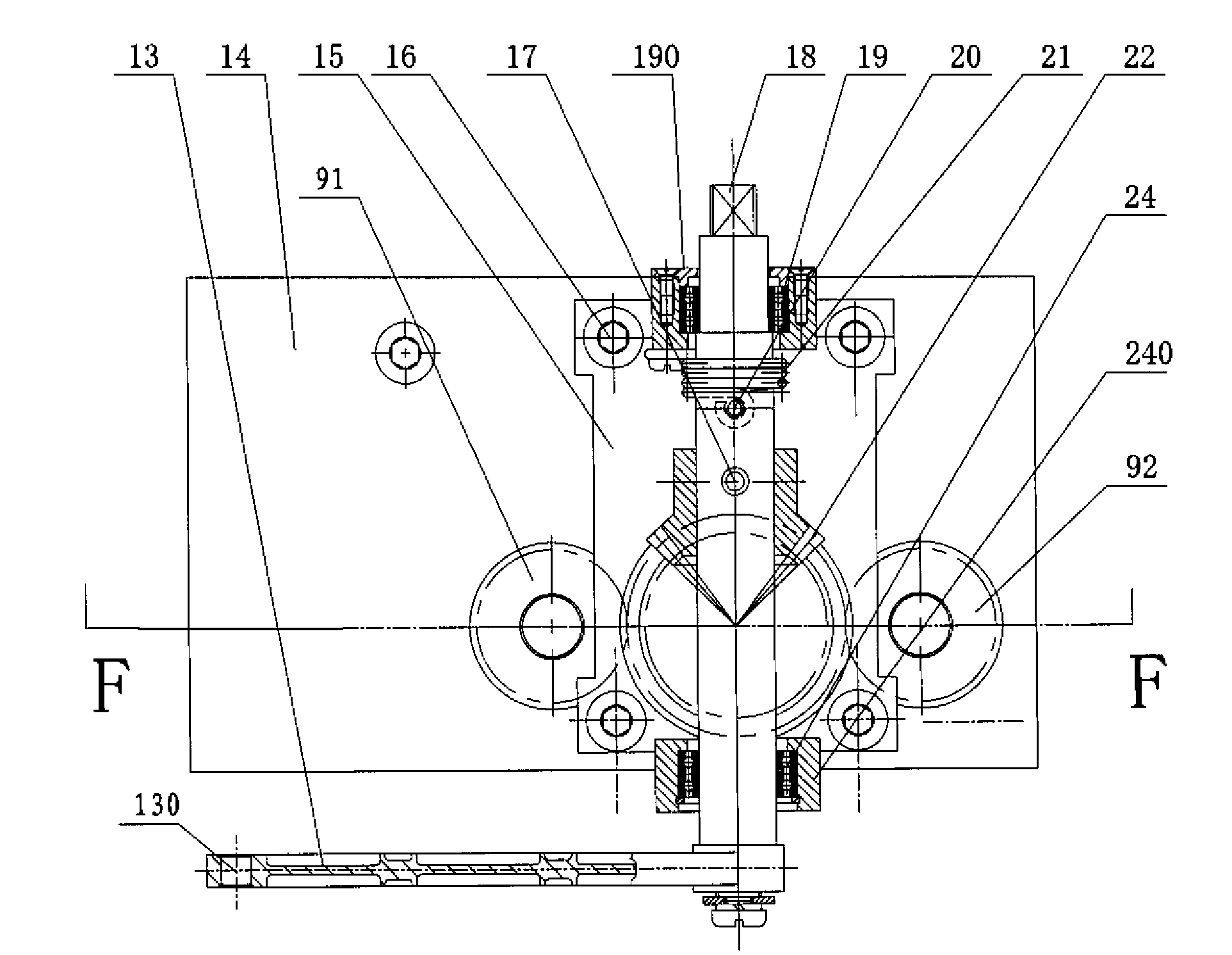
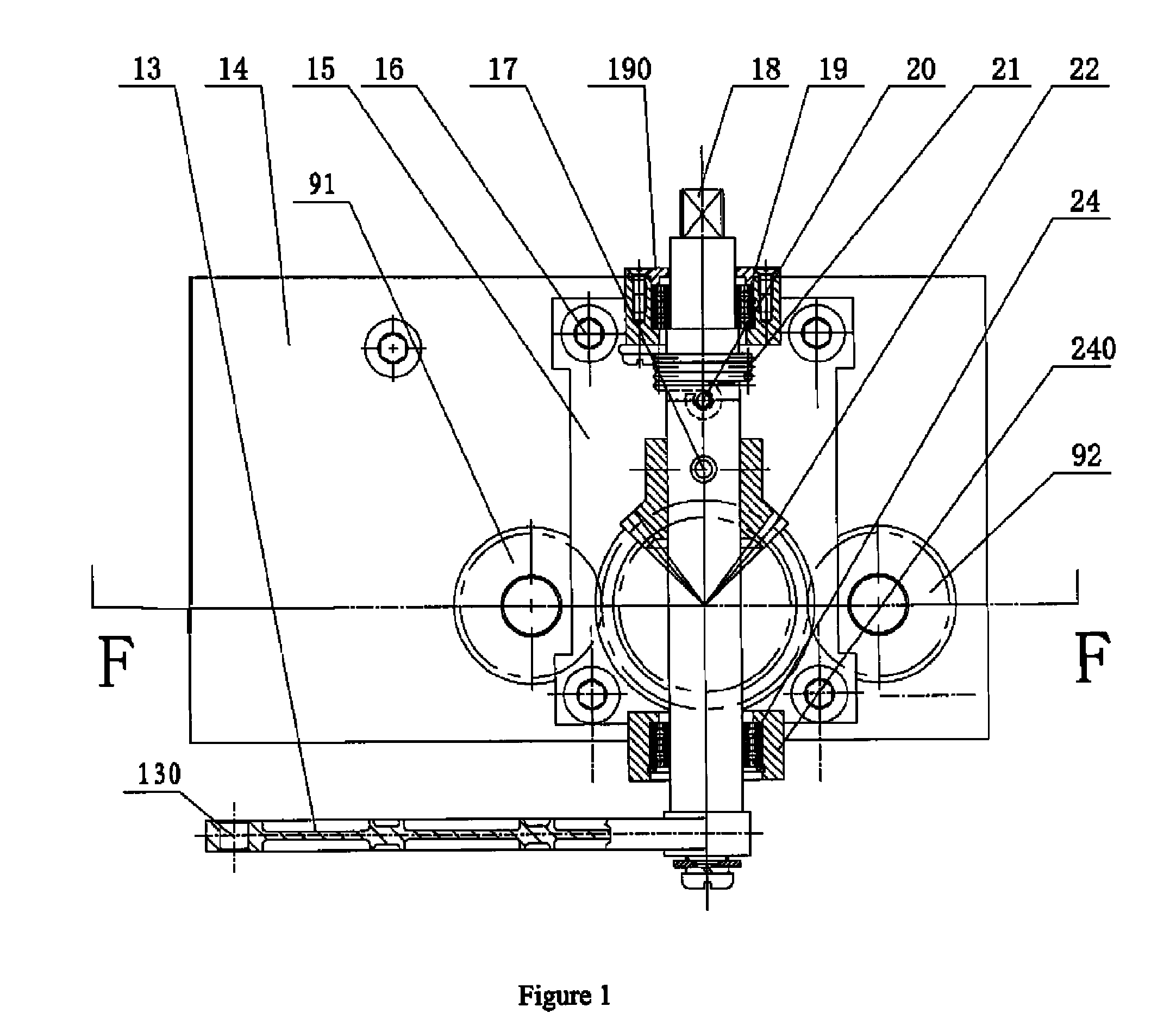
[0027]Referring to FIG. 1, in a fast clutch mechanism of a preferred embodiment of the present invention, a screw 16 is employed to secure a clutch bracket 15 onto an upper side of a transmission box 14. Bearing bases 190, 240 are installed on an upper end and a lower end of the clutch bracket 15 respectively. The bearing bases 190, 240 respectively include bearings 19, 24. A rotation shaft 18 is rotatably mounted between the bearings 19, 24. An end of the rotation shaft 18 is connected to an end of an operating shank 13. A free end of the operating shank 13 defines a through hole 130 therein. A rope (not shown) passes through the through hole 130 for pulling the operating shank 13. The operating shank 13 is used as a lever with the end of the operating shank 13 as a fulcrum, which makes it easy to pull the rope to enable the rotation shaft 18 to rotate. The operating shank 13 which works as a rotation actuating device and the rotation shaft 18 form a rotation device which provides ...


PUM


Abstract

A fast clutch mechanism for an industrial door is provided. A worm is connected to a motor shaft of the industrial door and meshes with a worm wheel which is rotatably mounted on an output shaft of a transmission box. The fast clutch mechanism includes: a clutch sleeve surrounding the output shaft and restricted to be slid axially on the shaft, one end of the sleeve being capable of engaging a corresponding surface of the worm wheel, while the other end having a ring portion extended outwardly; a rotation device including a rotation shaft and a rotation actuating device coupled with one end of the rotation shaft; bevel gear driving device which includes a primary bevel gear mounted on the rotation shaft and a secondary bevel gear engaging with the primary bevel gear; a differential device including a drive gear rotatable with the secondary bevel gear, two follower gears engaging with the drive gear, and two cam shift levers connecting respectively the two follower gears in an axial direction, the two cam shift levers resisting against the ring portion of the clutch sleeve so as to make the clutch sleeve slide between an engagement position and an disengagement position with the clutch assembly. The present invention has the advantage of realizing ease clutch operation on the ground, thus reducing potential dangers.

Description

BACKGROUND[0001]1. Field of the Invention[0002]The present invention relates to fast clutch mechanisms for industrial doors, and more particularly to a fast clutch mechanism for a door machine mounted at a height.[0003]2. Background[0004]A clutch mechanism for an industrial door is mainly used to enable a drive mechanism of a door machine to depart from the door machine when the door is subject to installation, maintenance or other urgent situations, thereby making it possible for the door to be pushed manually.[0005]Referring to FIG. 3, in a typical industrial door, one end of a motor shaft (not shown) is connected to a worm 23. An output shaft 1 of a transmission box 14 has a worm wheel 3 engaged with the worm 23. The worm wheel 3 is restrained in an axial direction of the output shaft 1, but is rotatable with respect to the shaft in circumferential direction. In other words, the worm wheel 3 is capable of rotate relative to the output shaft 1. Idle rotation of the worm wheel 3 ca...

Claims


Application Information

Patent Timeline
Patent Type & Authority Patents(United States)
IPC IPC(8): F16H1/16F16D21/00F16D19/00F16D13/00F16D23/00F16H1/20E05F15/00
CPCE05F15/603E05Y2201/214E05Y2201/244E05Y2900/11Y10T74/19614Y10T74/19828E05Y2800/26
Inventor WAN, WEI
Owner JIANGXI BAISHENG GATE & DOOR AUTOMATION
Why Eureka
Try Eureka