Light guide plate with diffusing protrusions

a technology of diffusing protrusions and guide plates, which is applied in the direction of instruments, lighting and heating apparatus, mechanical apparatus, etc., can solve the problems of reducing the optical performance of the backlight system b>100/b>, adding to the cost of raw materials and manufacturing, etc., and achieve excellent light diffusion

Inactive Publication Date: 2006-03-21
HON HAI PRECISION IND CO LTD
View PDF3 Cites 14 Cited by
  • Summary
  • Abstract
  • Description
  • Claims
  • Application Information

AI Technical Summary

Benefits of technology

[0009]It is therefore an objective of the present invention to provide a light guide plate which provides excellent diffusion of light.
[0011]The diffusing protrusions of the light guide plate can diffuse light beams emitting from the emitting surface of the transparent plate, in order to achieve a plane light source having even brightness. Moreover, the dots on the bottom surface of the transparent plate can scatter and reflect incident light beams, so as to totally eliminate internal reflection of light beams and make the light beams evenly emit from the emitting surface.

Problems solved by technology

However, the diffusion plate 120 is an extra element that adds to costs of raw materials and costs of manufacturing.
As a result, optical performance of the backlight system 100 is diminished.

Method used


Image

  • Light guide plate with diffusing protrusions
  • Light guide plate with diffusing protrusions
  • Light guide plate with diffusing protrusions

Examples


Embodiment Construction

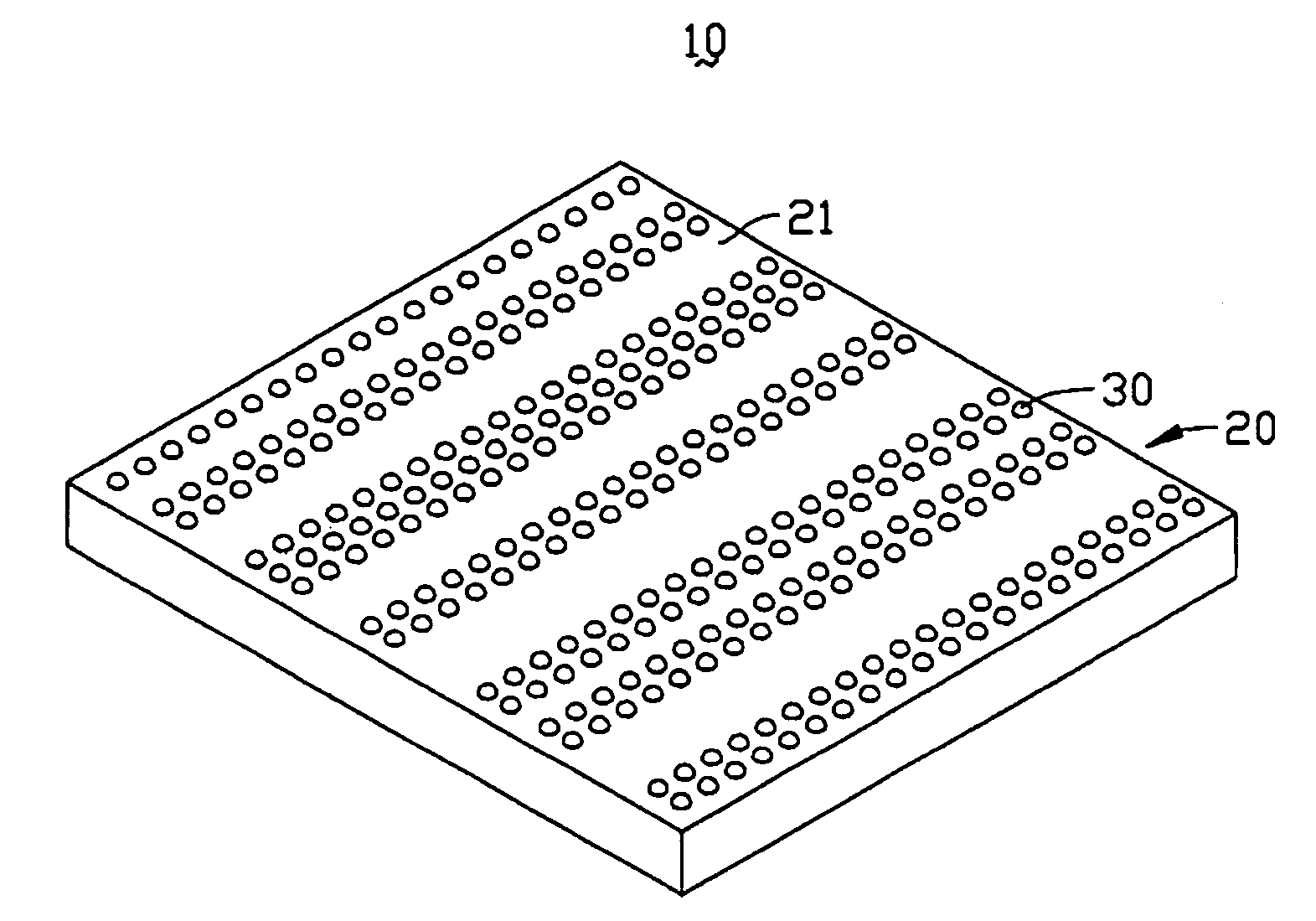
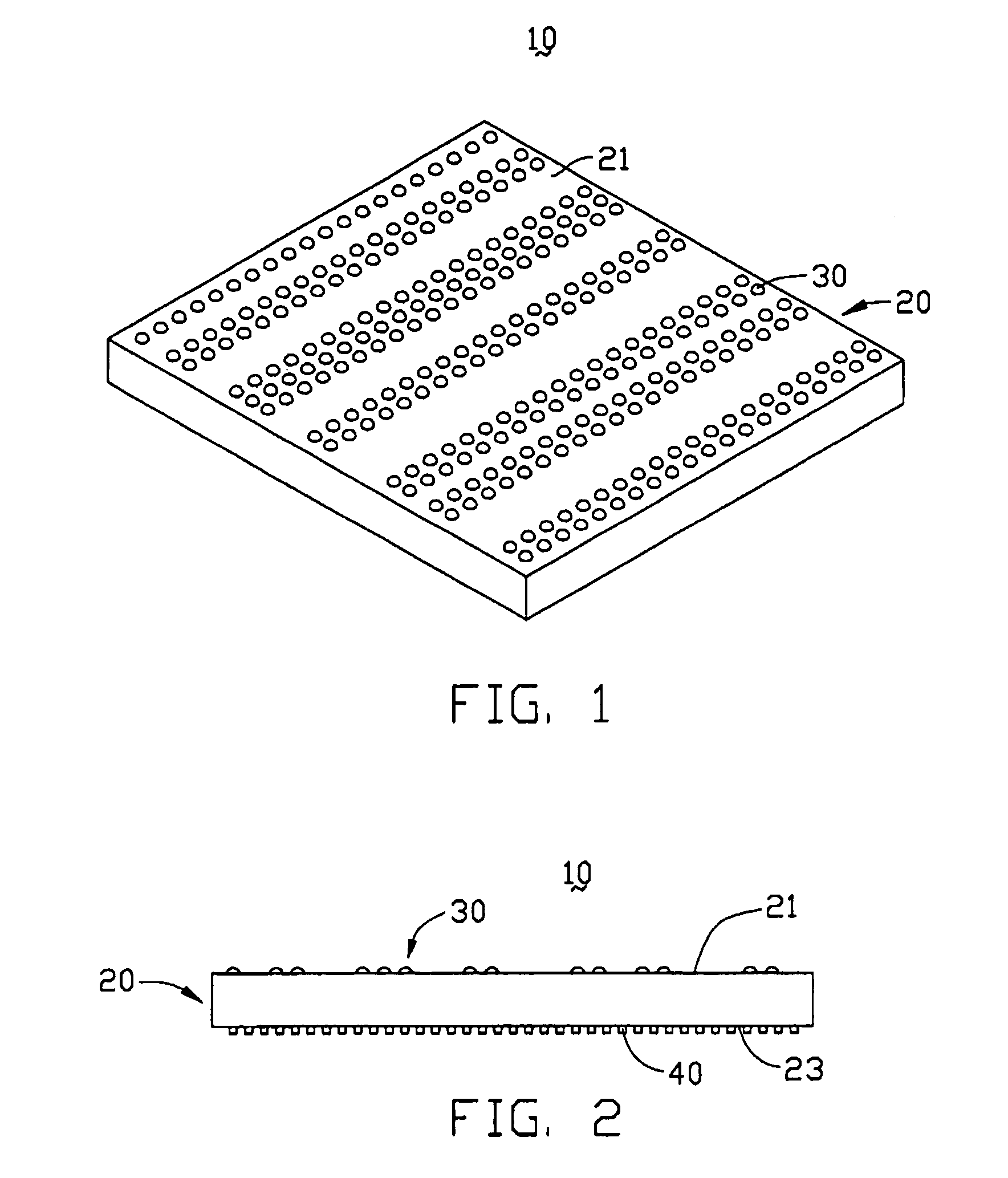
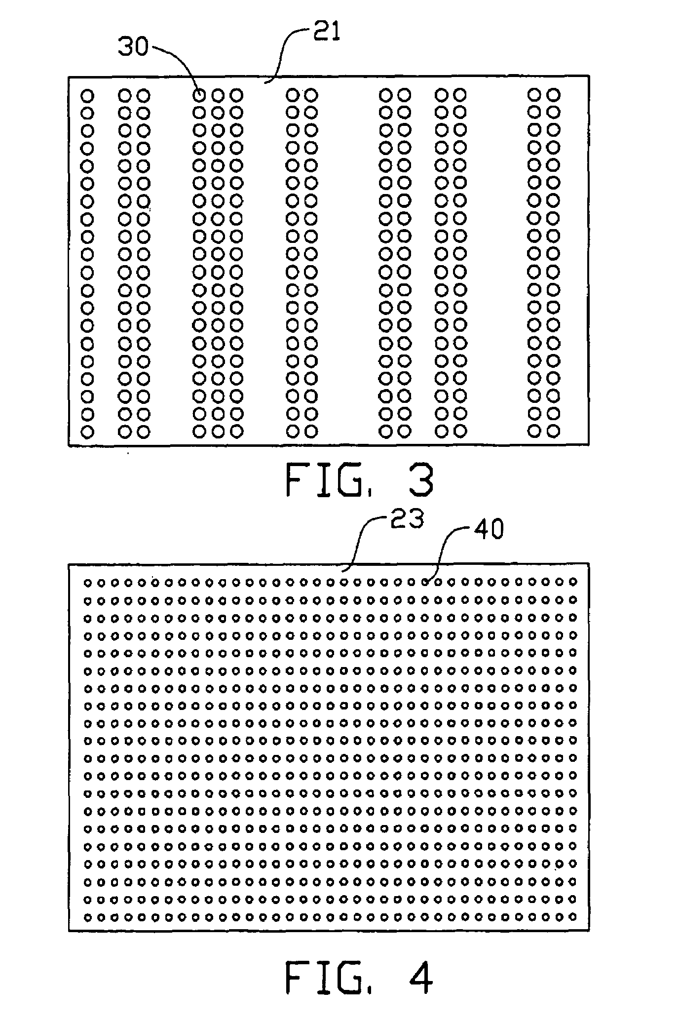
[0020]Referring to FIGS. 1, 2 and 3, a light guide plate 10 in accordance with a preferred embodiment of the present invention includes a transparent plate 20 on which a plurality of diffusing protrusions 30 is formed. The transparent plate 20 is generally a flat panel made from polymethyl methacrylate (PMMA). Alternatively, The transparent plate 20 may be generally cuneiform. The transparent plate 20 includes an incident surface (not labeled), an emitting surface 21, and a bottom surface 23. The incident surface faces a light source (not shown), and receives light beams from the light source. The light beams from the incident surface are then directed to and emitted from the emitting surface 21. The incident surface is perpendicular to the bottom surface 23, while the emitting surface 21 is opposite to the bottom surface 23.

[0021]The diffusing protrusions 30 are evenly distributed on the emitting surface 21, and are integrally formed with the transparent plate 20. In general, the d...


PUM


Abstract

A light guide plate (10) includes a transparent plate (20), and a plurality of diffusing protrusions (30). The transparent plate includes an emitting surface (21), and a bottom surface (23) opposite to the emitting surface. The diffusing protrusions are distributed evenly on the emitting surface of the transparent plate, and are integrated with the transparent plate. The diffusing protrusions are hemispherical or sub-hemispherical, and a diameter of each diffusing protrusion is in the range from 10 μm˜50 μm. The light guide plate provides high emitting brightness and uniformity. The diffusing protrusions can diffuse light beams emitting from the emitting surface of the transparent plate, in order to achieve a plane light source having even brightness. The present Invention also discloses a method for fabricating the light guide plate.

Description

BACKGROUND OF THE INVENTION[0001]1. Field of the Invention[0002]The present invention relates to light guide plates used in liquid crystal displays, and to methods for fabricating light guide plates.[0003]2. Description of the Prior Art[0004]A liquid crystal display is capable of displaying a clear and sharp image through millions of pixels of image elements. It has thus been applied to various electronic equipment in which messages or pictures need to be displayed, such as in mobile phones and notebook computers. However, liquid crystals in the liquid crystal display do not themselves emit light. Rather, the liquid crystals have to be lit up by a light source so as to clearly and sharply display text and images. The light source may be ambient light, or part of a backlight system attached to the liquid crystal display.[0005]A conventional backlight system generally comprises a plurality of components, such as a light source, a reflective plate, a light guide plate, a diffusion plat...

Claims


Application Information

Patent Timeline
Patent Type & Authority Patents(United States)
IPC IPC(8): F21V7/04F21V8/00G02B6/00
CPCG02B6/0036G02B6/0065G02B6/0043G02B6/0061
Inventor LEU, CHARLESCHEN, MI-CHIENYU, TAI-CHENGCHEN, GA-LANELIU, MING-HSUAN
Owner HON HAI PRECISION IND CO LTD
Why Eureka
Try Eureka