Hook fastener and method of making

a technology of hooks and fasteners, applied in the field of meshes, netting or strand elements, can solve the problems of complex process of deposited hook material onto the web, requiring precision manufacturing, and generally non-uniform formed web material having the hook material, etc., to achieve uniform machine handling properties, low manufacturing cost, and simple manufacturing.

Inactive Publication Date: 2006-03-21
3M INNOVATIVE PROPERTIES CO
View PDF30 Cites 56 Cited by
  • Summary
  • Abstract
  • Description
  • Claims
  • Application Information

AI Technical Summary

Benefits of technology

[0004]US2003 / 0009144 discloses a fastening material embedded within a flexible material to help present a cloth-like surface to the wearer or the caregiver (e.g., with a diaper) and to reduce the possibility of the fastener having exposed harsh edges. The method to achieve this, is again extremely complex, requiring a large deal of precision and has the same drawbacks associated with roll stability and dimensional stability when undergoing manufacturing and converting.
[0006]Many articles are made at high speed in order for the process to be economical. It is thus desirable for a manufacturer of these articles, which use a mechanical fastener, to mount a roll of the hook fastener material which has uniform machine handling properties to allow high-speed application of the mechanical fasteners. This is difficult with the current proposed hook type mechanical fasteners which also provide the benefits of flexibility, softness and breathability. Moreover, there is a need for improved methods to reliably and consistently make low manufacturing cost mechanical fasteners having the combined benefits of flexibility, softness and / or breathability.
[0007]The present invention is directed at providing a novel mechanical fastening cloth-like laminate, which is economical, and, exhibits ease, simplicity and mechanical stability for use in high speed manufacturing processes, and provides the desirable functional and aesthetic properties.BRIEF DESCRIPTION OF THE INVENTION

Problems solved by technology

The processes of depositing the hook material onto the web are generally complicated and require precision manufacturing.
The formed web material having the hook material is also generally non-uniform posing challenges for roll stability and dimensional stability during manufacturing of the continuous web itself and then delivering it as a hook component into a finished article.
Moreover the webs, where hook fastening material has been configured into discrete areas, creates the potential for skin irritation due to the rigid edges associated with each discrete patch of hook material.
In addition the cloth-like feel is limited to one side of the web material laminate since the hook patches are on one side of the nonwoven web.
The method to achieve this, is again extremely complex, requiring a large deal of precision and has the same drawbacks associated with roll stability and dimensional stability when undergoing manufacturing and converting.
The prongs can be formed by a screen printing type of process, but the process is generally limited to use of adhesive type polymers (polyesters) and still the hooks are easily detached from the substrate due to the limited contact area.
This is difficult with the current proposed hook type mechanical fasteners which also provide the benefits of flexibility, softness and breathability.

Method used


Image

  • Hook fastener and method of making
  • Hook fastener and method of making
  • Hook fastener and method of making

Examples


example 1

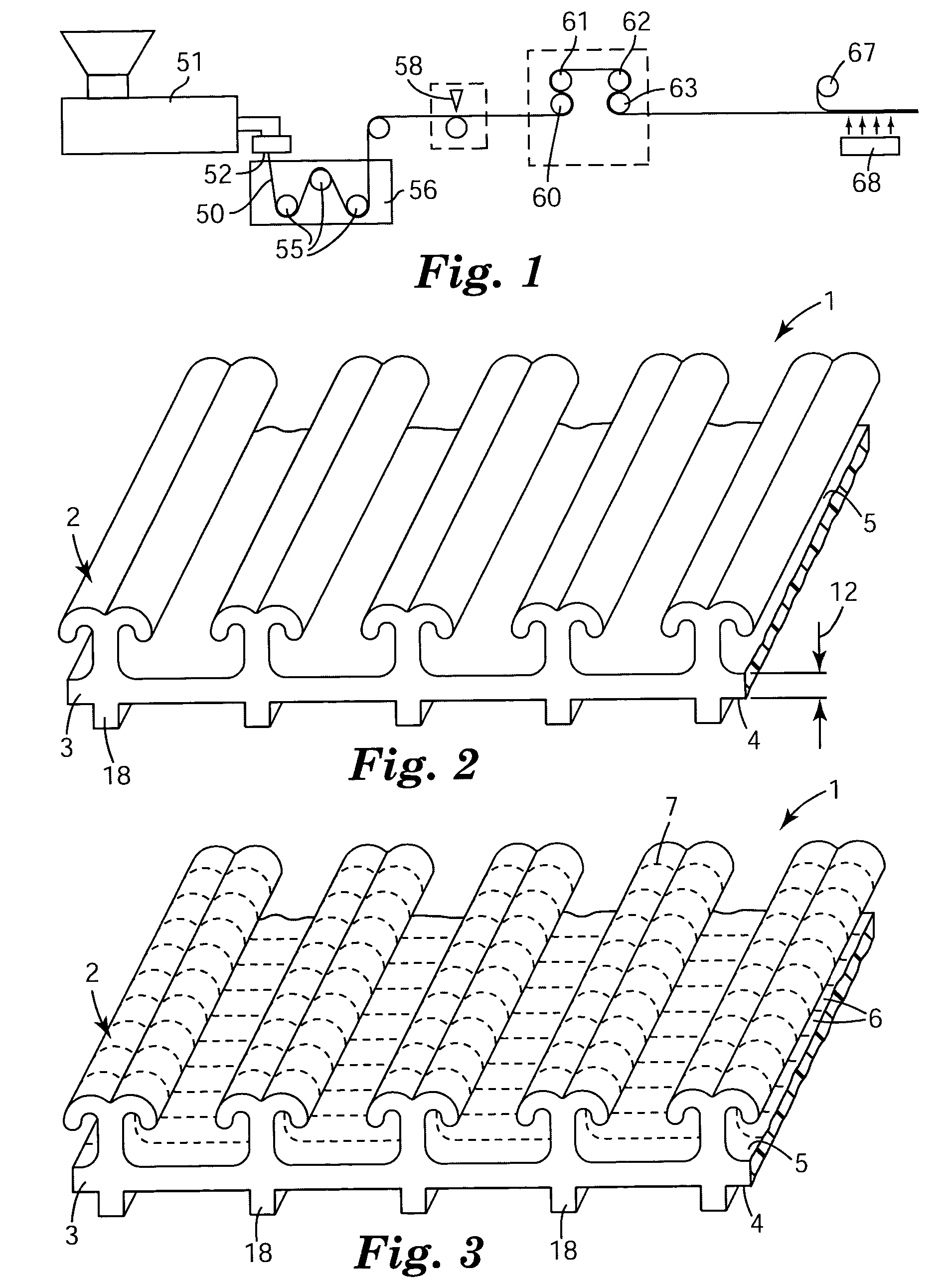
[0049]A mesh hook netting was made using apparatus similar to that shown in FIG. 1. A polypropylene / polyethylene impact copolymer (SRC7-644, 1.5 MFI, Dow Chemical) was extruded with a 6.35 cm single screw extruder (24:1 L / D) using a barrel temperature profile of 175° C.-230° C.-230° C. and a die temperature of approximately 230° C. The extrudate was extruded vertically downward through a die having an opening cut by electron discharge machining to produce an extruded profiled web similar to that shown in FIG. 2. The crossweb spacing of the upper ribs was 7.3 ribs per cm. After being shaped by the die, the extrudate was quenched in a water tank at a speed of 6.1 meter / min with the water being maintained at approximately 10° C. The web was then advanced through a cutting station where the upper ribs and the base layer (but not the lower ribs) were transversely cut at an angle of 23 degrees measured from the transverse direction of the web. The spacing of the cuts was 305 microns. Afte...

example 2

[0052]A hydroentangled composite web was made similar to that in Example 1 except the two nonwoven unbonded carded webs consisted of a blend of 95% Kosa T224 3d polyester fibers and 5% Kosa T254 2d polyester bicomponent fibers. The basis weight of the carded webs was 30 grams / meter2. The composite web had a cloth-like feel and appearance, and was very flexible and conformable.

example 3

[0053]A hydroentangled composite web having elastic properties was produced similar to the web in Example 1 except an additional elastomeric nonwoven web was used and a fibrillated hook material was used in place of the hook netting.

[0054]A hook web, available from 3M Company St. Paul, Minn. as KN-3425, was fibrillated using the following procedure. A 10 cm wide hook web was fed into a rotary cutting apparatus similar to that shown in FIG. 1 of U.S. Pat. No. 5,058,472. The apparatus consisted of intermeshing upper and lower steel rotary cutting rolls fitted with continuous cutting blades mounted around the periphery of the rolls. Spacers were used in between the blades to provide approximately 6 blades / cm in the lateral direction. The apparatus was operated manually with a hand crank to advance the hook web through the nip of the cutting apparatus at a nip pressure of approximately 70 kg / cm2 to introduce slits through the web in the down web direction. Due to the input web being thi...


PUM

PropertyMeasurementUnit
pressuresaaaaaaaaaa
pressuresaaaaaaaaaa
diametersaaaaaaaaaa

Abstract

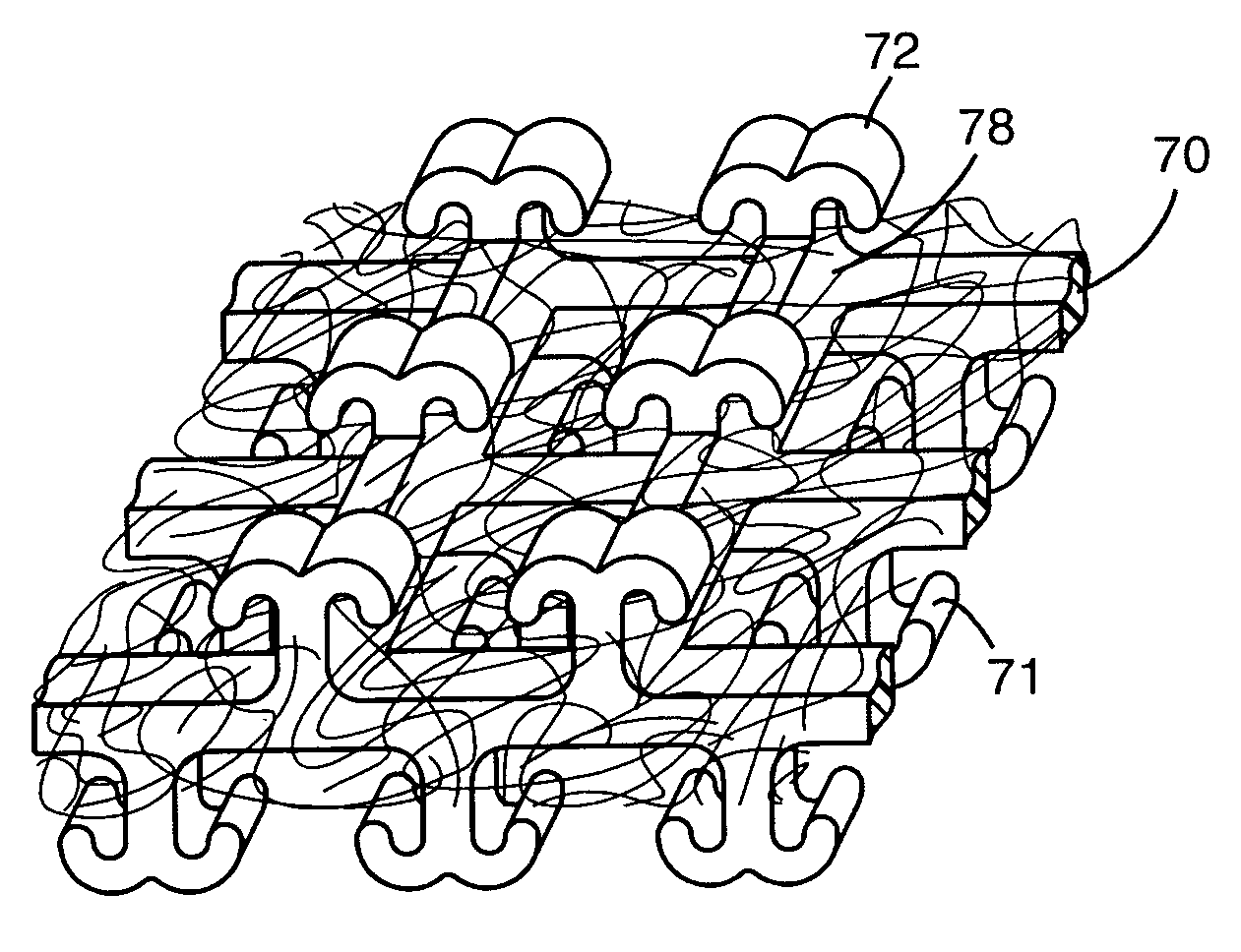
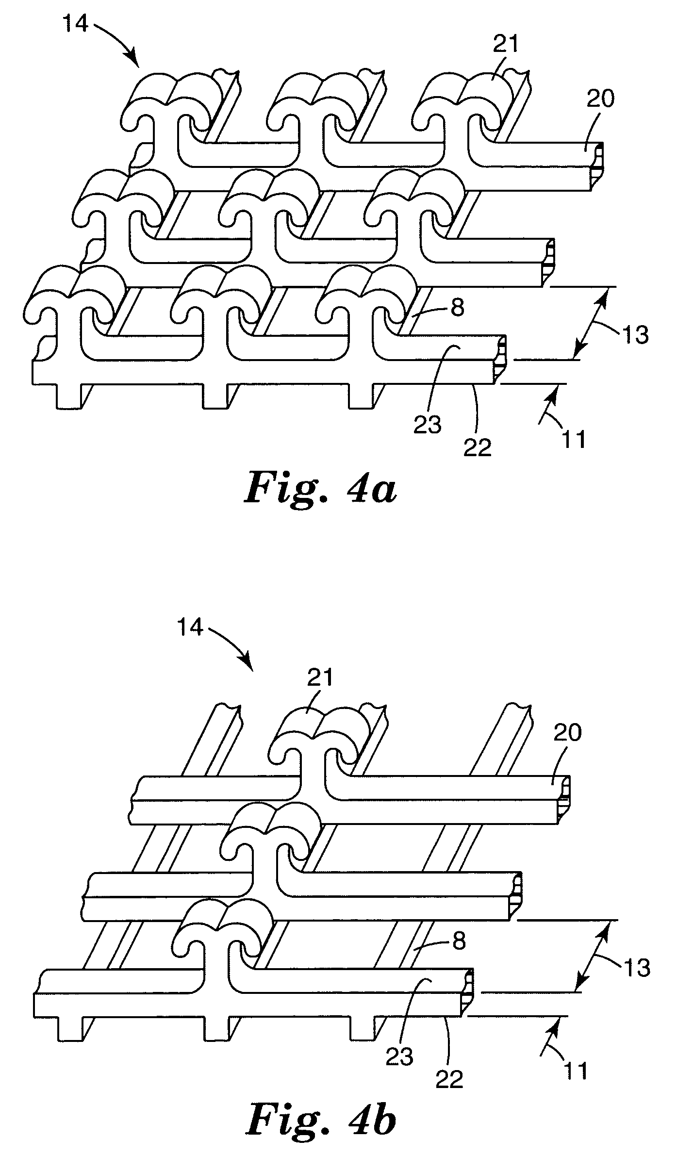
The present invention is directed at a hook mechanical fastener / fibrous composite comprising hook elements on hook containing backing elements or a netting embedded in a fibrous web. The hook elements preferably are on backing elements that are connected or integral and can be strands oriented at angles to each other in a net form. The backing elements generally have a first outer face and a second outer face. The backing elements on at least one of the first or second outer faces have a plurality of hook elements. The hook containing backing elements are embedded within a fibrous web, preferably by hydroentangling the fibers around the backing element, preferably without use of auxiliary attachment means such as adhesives or point bonding.

Description

SUMMARY OF THE INVENTION[0001]The present invention concerns a mesh, netting or strand element including hook fasteners incorporated into a fibrous web for use with hook and loop fasteners.[0002]Hook type mechanical fasteners typically have backing formed from relatively thick and rigid backing materials. Recent attempts in the art suggest that flexible backings are desirable for hook fasteners and have proposed hooks or discrete hook patches on a flexible backing. US 2001 / 0016245 discloses a web of material, generally a nonwoven web, having a multiplicity of discrete polymer regions with a plurality of stems extending from each polymer region. Generally, discrete quantities of polymeric material are deposited and fused to the web by entangling or encapsulating the fibers that make up the nonwoven web, and simultaneously or subsequently formed into stems or hooks. A similar approach is also discussed in WO02 / 096233.[0003]Flexible and generally breathable webs with isolated areas or ...

Claims


Application Information

Patent Timeline
Patent Type & Authority Patents(United States)
IPC IPC(8): B32B3/06A44B18/00A61F13/62D04H13/00
CPCA44B18/0015D04H13/003A61F13/62Y10T428/24017A61F13/625A44B18/00
Inventor TUMAN, SCOTT J.SETH, JAYSHREELINDQUIST, TIMOTHY J.ISTA, TROY K.AUSEN, RONALD W.
Owner 3M INNOVATIVE PROPERTIES CO
Why Eureka
Try Eureka