Spectrally tunable detector

a detector and spectrally tunable technology, applied in the field of tunable detectors, can solve the problems of not being able to dynamically change the operative wavelength during operation, and not being able to tunable wavelengths

Inactive Publication Date: 2006-03-21
HONEYWELL INT INC
View PDF29 Cites 41 Cited by
  • Summary
  • Abstract
  • Description
  • Claims
  • Application Information

AI Technical Summary

Benefits of technology

[0005]The tunable bandpass filter may include a top plate and a bottom plate. Both the top plate and the bottom plate may be adapted to include a reflective region, and may be separated by a separation gap to form a Fabry-Perot cavity. When so provided, the tunable bandpass filter may be selectively tuned to a desired bandpass wavelength by moving the top plate and / or bottom plate relative to one another to change the separation gap. This movement can be driven by an electrostatic force. The range of movement of the top and / or bottom plate can determine the spectral range of the selected wavelengths. In some embodiments, a lens is positioned adjacent the tunable bandpass filter to help direct and / or shape the incoming light beam.

Problems solved by technology

A limitation of many of these filters is that they are not wavelength tunable.
That is, the operative wavelength cannot be dynamically changed during operation to select a different optical wavelength.

Method used


Image

  • Spectrally tunable detector
  • Spectrally tunable detector
  • Spectrally tunable detector

Examples


Embodiment Construction

[0026]The following description should be read with reference to the drawings wherein like reference numerals indicate like elements throughout the several views. The detailed description and drawings are presented to show embodiments that are illustrative of the claimed invention.

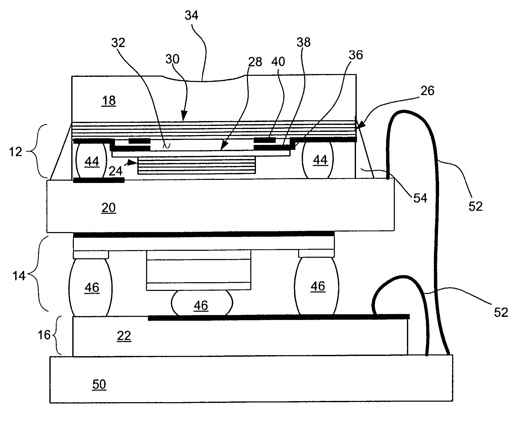
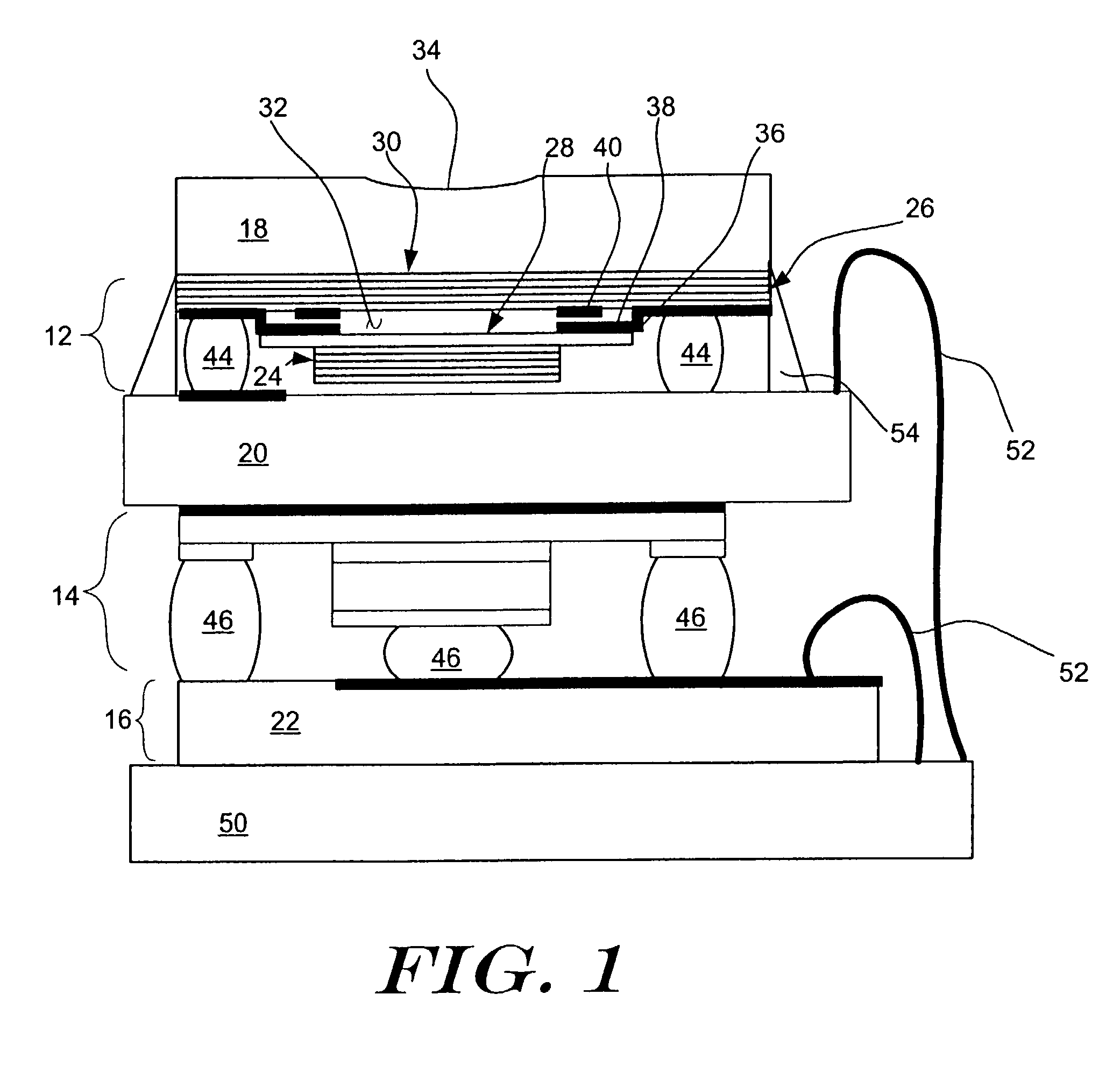
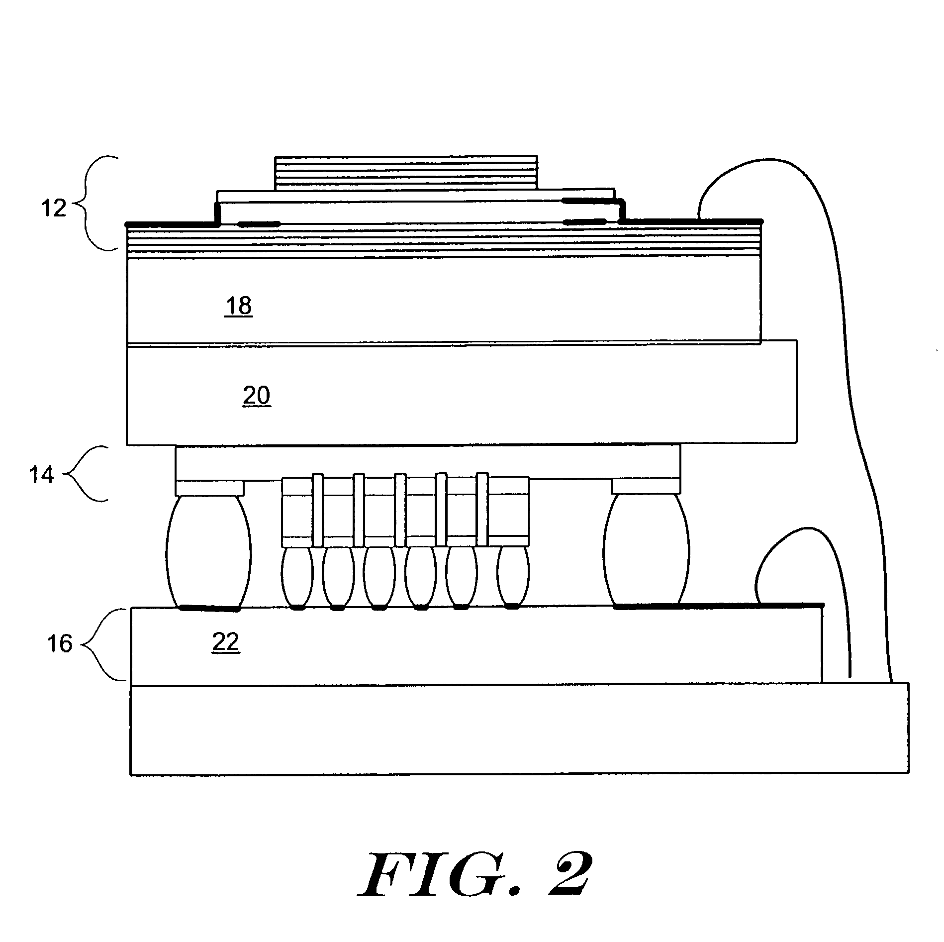
[0027]FIG. 1 is a schematic cross-sectional side view of an illustrative tunable bandpass detector 10 in accordance with the present invention. The illustrative tunable bandpass detector 10 includes a tunable bandpass filter 12, a detector 14 and readout electronics 16, each supported by a different substrate. For example, the tunable bandpass filter 12 is supported by a first substrate 18, the detector 14 is supported by a second substrate 20, and the readout electronics 16 are supported by a third substrate 22.

[0028]In the illustrative embodiment, the tunable bandpass filter 12 includes a Micro Electro Optical Mechanical System (MEOMS) etalon. The MEOMS includes a top plate 24 and a bottom plate 26. The ...


PUM


Abstract

A spectrally tunable optical detector and methods of manufacture therefore are provided. In one illustrative embodiment, the tunable optical detector includes a tunable bandpass filter, a detector and readout electronics, each supported by a different substrate. The substrates are secured relative to one another to form the spectrally tunable optical detector.

Description

FIELD OF THE INVENTION[0001]The present invention relates to tunable detectors, and more specifically, to spectrally tunable detectors and methods of manufacture therefore.BACKGROUND OF THE INVENTION[0002]Optical filters are commonly used in a wide variety of applications. For example, optical filters are used to provide separate optical “channels” in optical fiber networks. Optical filters are also used to monitor the spectral emission from the power plants and engines to provide a level of combustion monitoring and control. Optical filters can also be used in biological particle identification systems to provide spectral resolution of the fluorescence needed for high levels of discrimination of biological materials. These are just a few of the many applications for optical filters.[0003]Many optical filters are formed from thin films that reflect or transmit a narrow band of wavelengths. In many cases, such filters are constructed from several hundred layers of stacked narrow band...

Claims


Application Information

Patent Timeline
Patent Type & Authority Patents(United States)
IPC IPC(8): H01J40/14G01B11/27G01J3/36G01J3/427G01J5/20G02B5/28G02B26/00
CPCG01B11/272G01J3/36G01J3/427G01J5/20G02B5/284G02B26/001H01L27/14621H01L31/02024H01L31/0232H01L2224/48091H01L31/02162H01L2224/13H01L2924/00014G01J3/26H01L31/02325H01L2224/05568H01L2224/05573
Inventor COLE, BARRETT E.HIGASHI, ROBERT E.SUBRAMANIAN, ARUNKUMARKRISHNANKUTTY, SUBASH
Owner HONEYWELL INT INC
Why Eureka
Try Eureka