Capacitance detection apparatus

a technology of capacitive detection and detection apparatus, which is applied in the direction of resistance/reactance/impedence, pulse technique, instruments, etc., can solve the problems of detection sensitivity lowering, sensitivity lowering, and the capacitive detection apparatus described in u.s. pat. no. 3,886,447a cannot be adapted to the unlocking sensor

Active Publication Date: 2006-03-21
AISIN SEIKI KK
View PDF11 Cites 45 Cited by
  • Summary
  • Abstract
  • Description
  • Claims
  • Application Information

AI Technical Summary

Problems solved by technology

Therefore, the capacitance detection apparatus described in U.S. Pat. No. 3,886,447A can not be adapted to the unlocking sensor provided in the outside handle for the vehicle door having the sensor electrode and the other end of the capacitor to be measured is connected to ground or a low impedance portion such as free space equivalent to ground.
Further, in case that there are a leak resistance parallel to the capacitor to be measured, in other words, the unlock sensor electrode is in highly humid condition or wet with water, the capacitor to be measured is discharged except when the both ends of the capacitor to be measured are connected to the DC voltage source, and the standard capacitor is discharged when the both ends of the capacitor to be measured are connected to the standard capacitor, which causes a sensitivity lowering.
However, in case that there is the leak resistance parallel to the capacitor to be measured, the standard capacitor and the capacitor to be measured are discharged, which causes detection sensitivity lowering, similar to the known art described in U.S. Pat. No. 3,886,447A.
As a result, the voltage measurement of the standard capacitor becomes complex and the measured voltage becomes unstable.
Therefore, in the capacitance detection apparatus described in U.S. Pat. No. 6,466,036A, the capacitance of the one sensor electrode is influenced by the other sensor electrode being touched by the human body through the parasitic capacitance, which causes an error detection of the trigger of the locking.

Method used


Image

  • Capacitance detection apparatus
  • Capacitance detection apparatus
  • Capacitance detection apparatus

Examples


first embodiment

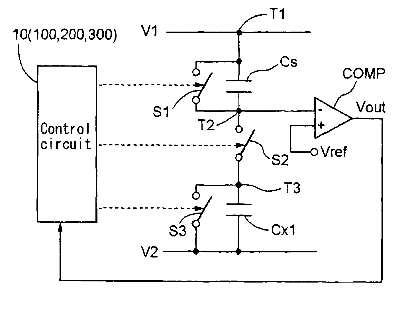
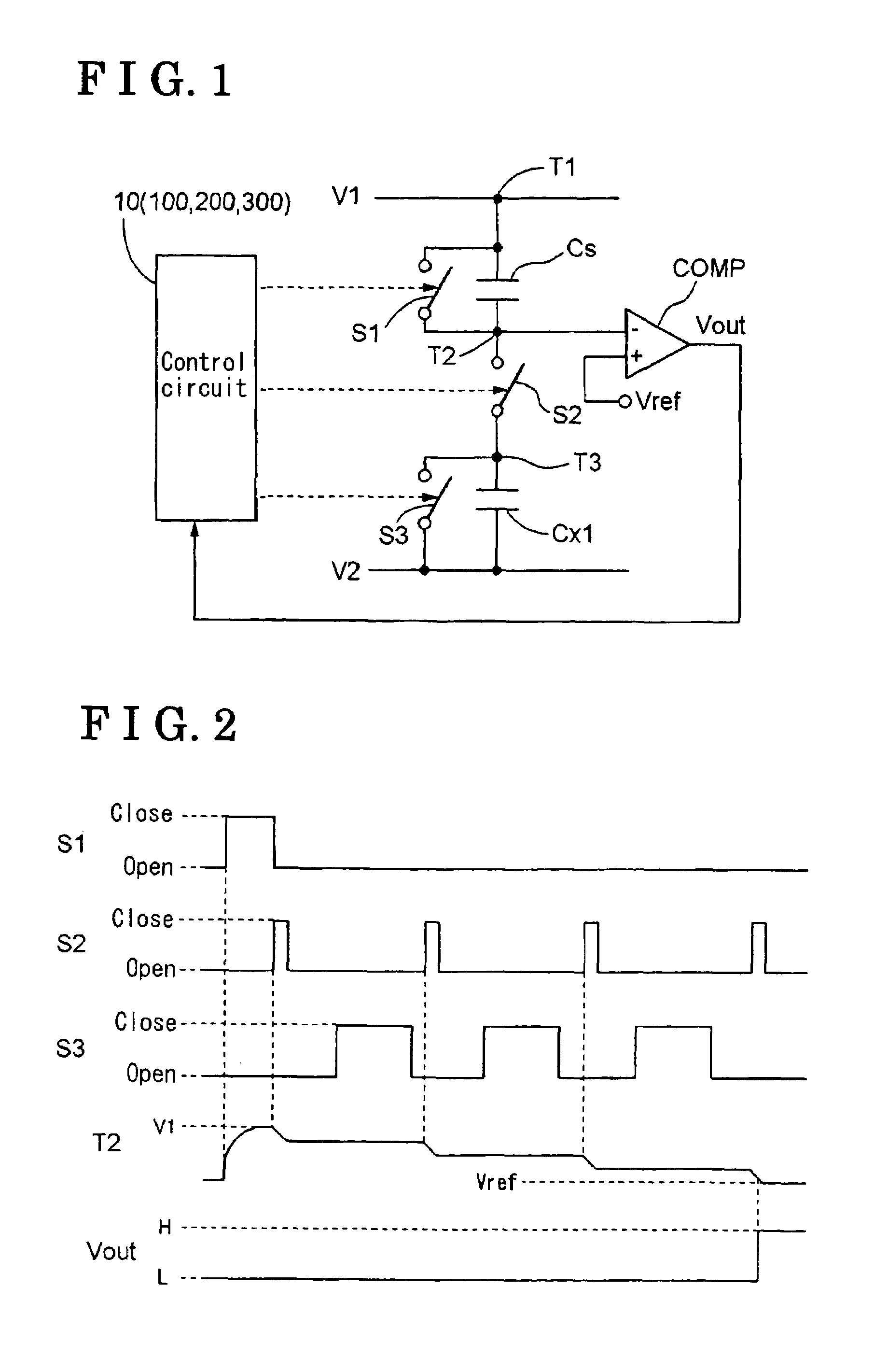
[0030]the present invention will be explained as follows. As shown in FIG. 1, a capacitance detection apparatus includes a first open / close switch provided between both ends of a standard capacitor Cs, a second open / close switch provided between one end T3 of a first capacitor to be measured Cx1 and the other end T2 of the standard capacitor Cs, and a third open / close switch S3 provided between both ends T3, V2 of the first capacitor to be measured Cx1. One end of the standard capacitor Cs is connected to a first voltage source V1. The other end of the first capacitor to be measured Cx1 is connected to a second voltage source V2 or free space. The capacitance detection apparatus further includes a comparator COMP serving as a voltage measurement means for measuring a voltage at the other end T2 of the standard capacitor Cs. Here, the first voltage source V1 is an output of a constant-voltage circuit. The second voltage source V2 is an earth (ground). The free space is a low impedanc...

second embodiment

[0040]the present invention will be explained as follows.

[0041]In the second embodiment, the capacitance detection apparatus includes two capacitors to be measured (the first capacitor to be measured Cx1 and a second capacitor to be measured Cx2). In the second embodiment, as shown in FIG. 6, the capacitance detection apparatus includes a fourth open / close switch S4 provided between an other end T4 of the second capacitor to be measured Cx2 and the other end T2 of the standard capacitor Cs, and a fifth open / close switch S5 provided between both ends T3, V2 of the second capacitor to be measured Cx2. One end of the second capacitor to be measured Cx2 is connected to the second voltage source V2 (serving as a third voltage source) or free space. In the embodiment, single voltage source V2 acts as both the second voltage source and the third voltage source.

[0042]Then, as shown in FIG. 7, the switch control means 100 performs the second switching control performing the first switching o...


PUM


Abstract

A capacitance detection apparatus includes a first open / close switch provided between both ends of a standard capacitor, one end of the standard capacitor being connected to a first voltage source, a second open / close switch provided between one end of a first capacitor to be measured and the other end of the standard capacitor, the other end of the first capacitor to be measured being connected to a second voltage source or free space, a third open / close switch provided between both ends of the first capacitor to be measured, a voltage measurement means for measuring voltage of the other end of the standard capacitor, a switch control means for performing a first switching control performing a first switching operation to open the first open / close switch after closing thereof, performing a second switching operation to open the second open / close switch after closing thereof, and a third switching operation to close the third open / close switch after closing thereof, wherein the second and third switching operations are repeatedly performed after the first switching operation, a counting means for counting the number of repetition of the second switching operation, and a judging means for judging a change of the capacitance of the first capacitor to be measured according to the number of repetition of the second switching operation, which is the number counted by the counting means during the voltage of the other end of the standard capacitor measured by the voltage measurement means being changed from an initial voltage after the first switching operation by a predetermined magnitude.

Description

CROSS REFERENCE TO RELATED APPLICATIONS[0001]This application is based on and claims priority under 35 U.S.C. §119 to Japanese Patent Application 2003-341063, filed on Sep. 30, 2003, the entire content of which is incorporated herein by reference.FIELD OF THE INVENTION[0002]This invention generally relates to a capacitance detection apparatus, more particularly, this invention generally relates to a capacitance detection apparatus for detecting an unknown capacitance and a change of the capacitance of a capacitor to be measured.BACKGROUND[0003]A capacitance detection apparatus is adapted to a triggering detection for an unlocking operation in a system for controlling an open / close of a door for a vehicle, such as an automobile. Specifically, when a user approaches the vehicle, an ID code certification is performed between the vehicle and a mobile system of the user. Then, the vehicle becomes a permission mode for unlocking. After that, when the user touches an unlocking sensor (elec...

Claims


Application Information

Patent Timeline
Patent Type & Authority Patents(United States)
IPC IPC(8): G01R27/26
CPCG01R27/2605H03K17/955H03K2217/960715
Inventor INABA, HISASHIKURACHI, KOHEIHATANO, RIKUO
Owner AISIN SEIKI KK
Why Eureka
Try Eureka