Multimode imaging system for generating high quality images

a multi-mode, high-quality technology, applied in the field of imaging, can solve the problems of difficult positioning and use of the ct system, image superposition artifacts, etc., and achieve the effect of convenient and fast access

Inactive Publication Date: 2006-03-21
GENERAL ELECTRIC CO
View PDF26 Cites 174 Cited by
  • Summary
  • Abstract
  • Description
  • Claims
  • Application Information

AI Technical Summary

Benefits of technology

[0014]The above described multimode imaging system generates various types of images for the object. Such system also enables easy

Problems solved by technology

The images, however, have significant super position artifacts.
The translation of the object through the gantry, in a

Method used


Image

  • Multimode imaging system for generating high quality images
  • Multimode imaging system for generating high quality images
  • Multimode imaging system for generating high quality images

Examples


Embodiment Construction

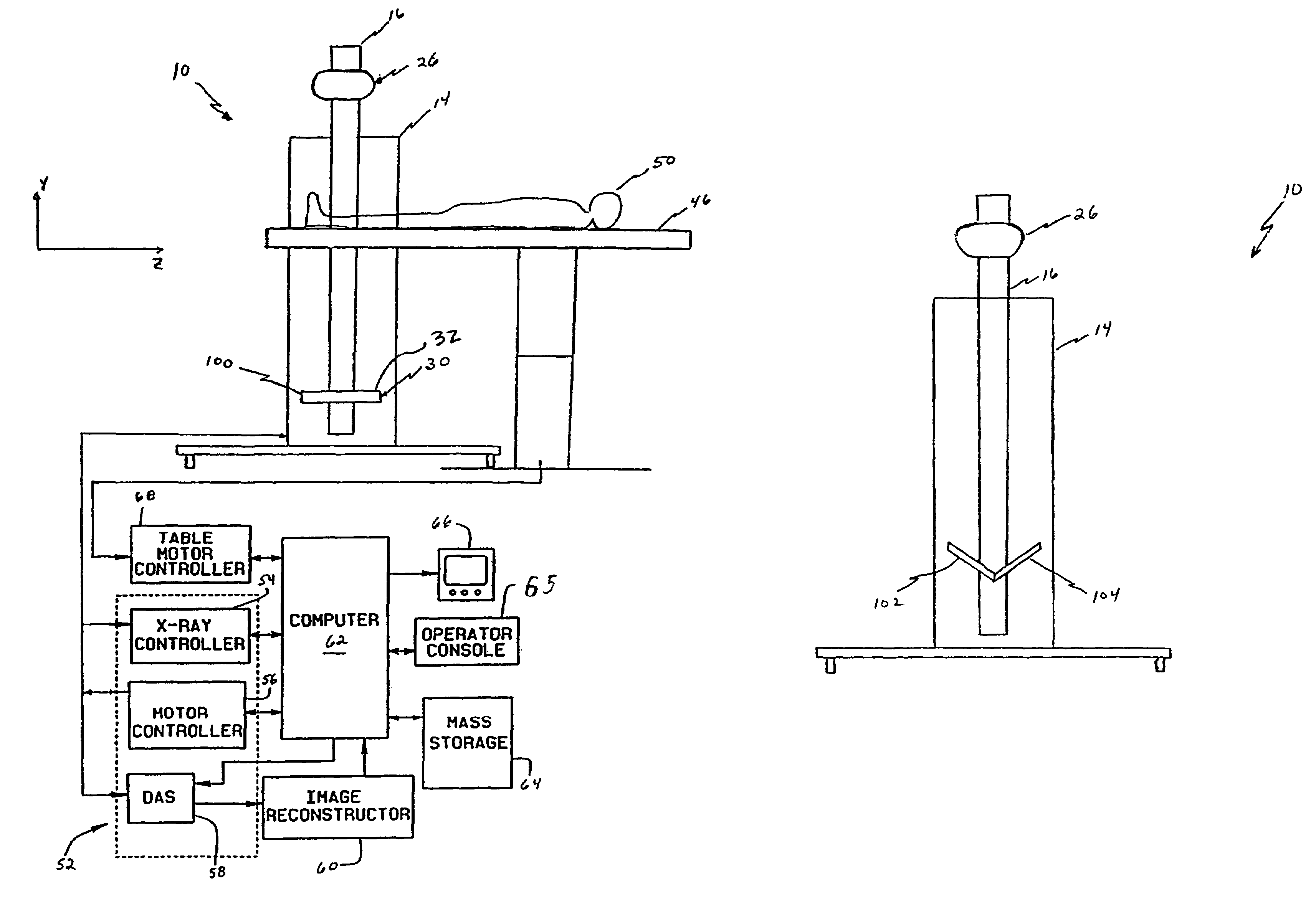
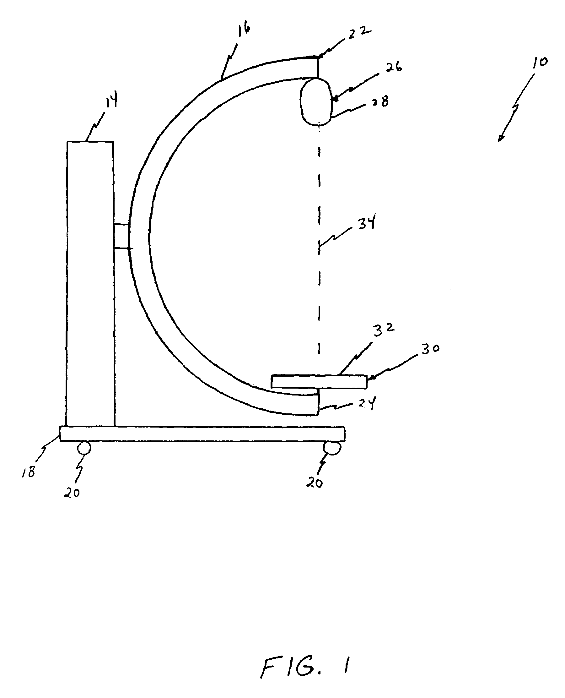
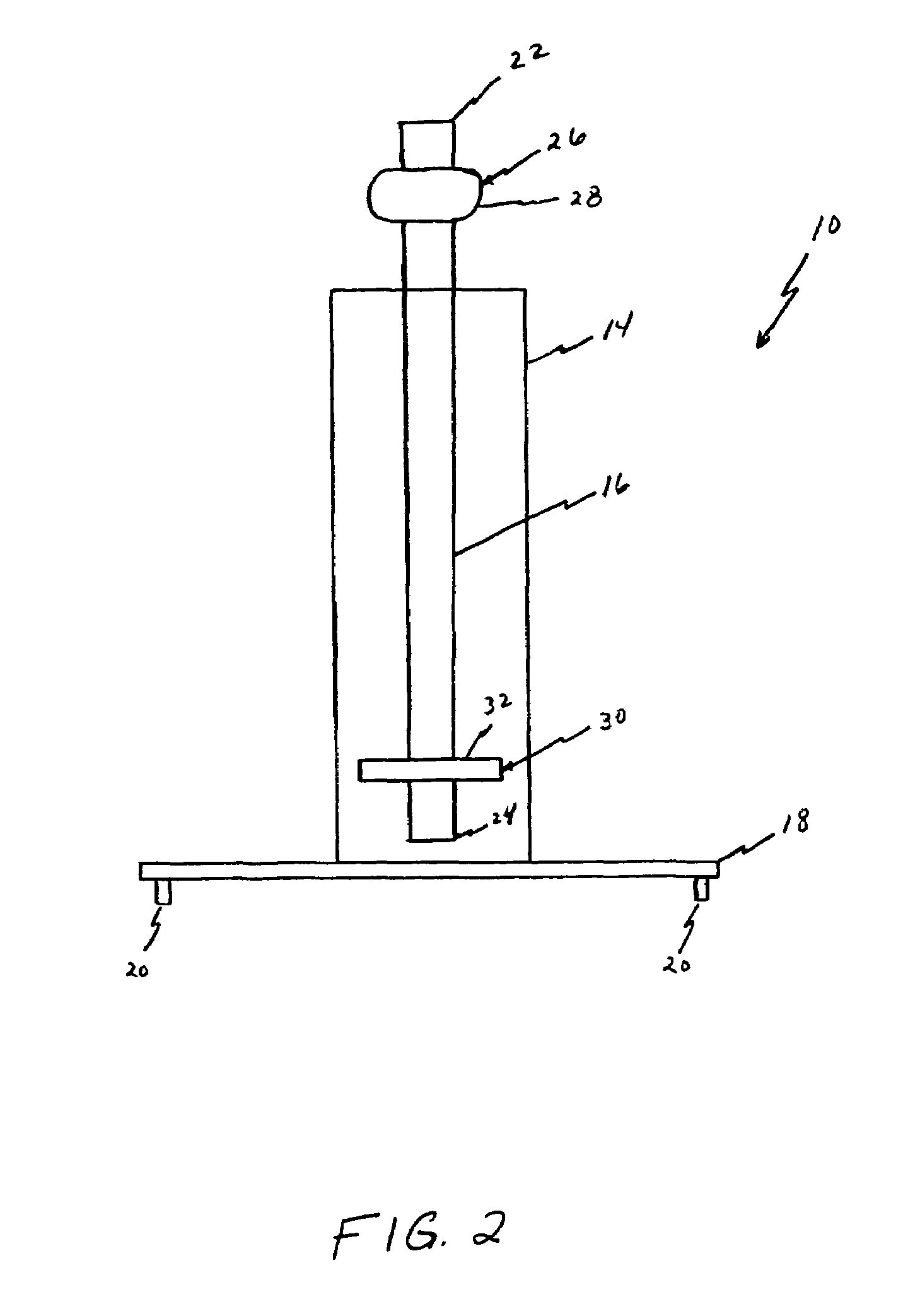
[0024]Referring to FIGS. 1 and 2 and in one embodiment, a multimode imaging system 10 is shown as including a base 14 and a positioning means 16. In one embodiment, base 14 extends from a portable platform 18 having a plurality of wheels 20, or other similar position altering devices, so that system 10 is movable relative to an object to be imaged (not shown in FIGS. 1 and 2). In an alternative embodiment, base 14 is movably coupled and extends from a fixed surface, i.e., a wall (not shown). In one embodiment positioning means 16 includes an arm which is movably coupled to base 14 and includes a first end portion 22 and a second end portion 24. More specifically, arm 16 rotates relative to base 14 about an axis of rotation and moves relative to base 14 to alter the respective distances between arm first end portion 22 and base 14 and arm second end portion 24 and base 14. An x-ray source assembly 26 is movably coupled to arm first end portion 22. X-ray source assembly 26 includes an...


PUM


Abstract

The present invention, in one form, is a multimode imaging system which, in one embodiment, includes a substantially C-shaped arm movably coupled to a movable base to reduce difficulty of scanning an object. A source assembly having a x-ray source and a detector assembly having a detector are movably coupled to the arm. The source assembly and the detector assembly are independently movable relative to each other and to the arm. In one embodiment, an operator selects one or more modes of operation of the imaging system so that various types of image data are displayed.

Description

CROSS REFERENCE TO RELATED APPLICATIONS[0001]This application claims the benefit of U.S. Provisional Application No. 60 / 114,479, filed Dec. 31, 1998.BACKGROUND OF THE INVENTION[0002]This invention relates generally to imaging and, more particularly, to scalable multislice imaging systems.[0003]In at least some imaging systems generally referred as computed tomography (CT) systems, an x-ray source projects a fan-shaped beam which is collimated to lie within an X-Y plane of a Cartesian coordinate system and generally referred to as the “imaging plane”. The x-ray beam passes through the object being imaged, such as a patient. The beam, after being attenuated by the object, impinges upon an array of radiation detectors. The intensity of the attenuated beam radiation received at the detector array is dependent upon the attenuation of the x-ray beam by the object. Each detector element of the array produces a separate electrical signal that is a measurement of the beam attenuation at the ...

Claims


Application Information

Patent Timeline
IPC IPC(8): G01N23/00A61B6/00A61B6/03
CPCA61B6/032A61B6/4405A61B6/588A61B6/4452A61B6/4441
Inventor SENZIG, ROBERT F.HE, HUI DAVID
Owner GENERAL ELECTRIC CO
Why Eureka
Try Eureka