Screwdriver with screw holder

a screw driver and screw technology, applied in screwdrivers, wrenches, osteosynthesis devices, etc., can solve the problems of screw drivers that screw drivers are not suitable for very small screws, and screw drivers are not suitable for introducing bone screws or pedicles

Inactive Publication Date: 2006-03-28
SYNTHES USA
View PDF11 Cites 13 Cited by
  • Summary
  • Abstract
  • Description
  • Claims
  • Application Information

AI Technical Summary

Benefits of technology

[0008]The advantages, achieved with the invention, can be seen essentially therein that, due to the inventive configuration of the spring element, a small overall depth of the front segment of the shaft is attainable so that screws with heads of low height or with recesses of small depth for accommodating the screwdriver can be used, the front segment of the shaft may be prismatic or cylindrical, as a result of which, in comparison to conical shaft segments, a maximum transfer of force can be exerted on the screw (the so-called “cam out” effect being avoided), the spring element can also be installed subsequently on conventional commercial screw drivers, a screw-holding sleeve is not necessary, so that it is possible to manipulate these screwdriver with one hand, the device can be produced easily, so that a low price is possible and because only a single, radial borehole is required in the front segment of the shaft, the spring element can also be used for the smallest screws and accordingly also for screws in maxillofacial, hand and foot surgery.
[0019]In a further embodiment of the inventive screwdriver, the recess has a ledge at a depth T, measured from the corner or tip, the depth T being equal to or greater than the length of the spring element, which is parallel to the longitudinal axis of the spring element, so that the spring element does not protrude beyond the tip, corner or curvature of the front segment of the shaft. By these means, it can be avoided that the spring element is pushed further into the recess as the front segment of the shaft is inserted into the seat for the screwdriver at the screw head.

Problems solved by technology

If the openings in the soft parts are very small, non-pointed forceps, for example, are then no longer suitable for introducing bone screws or pedicle screws.
It is a disadvantage of this development of the elastic means that the boreholes for accommodating the elastic means are configured in a relatively complicated manner and that therefore the screw driver is unsuitable for very small screws.

Method used


Image

  • Screwdriver with screw holder
  • Screwdriver with screw holder
  • Screwdriver with screw holder

Examples


Embodiment Construction

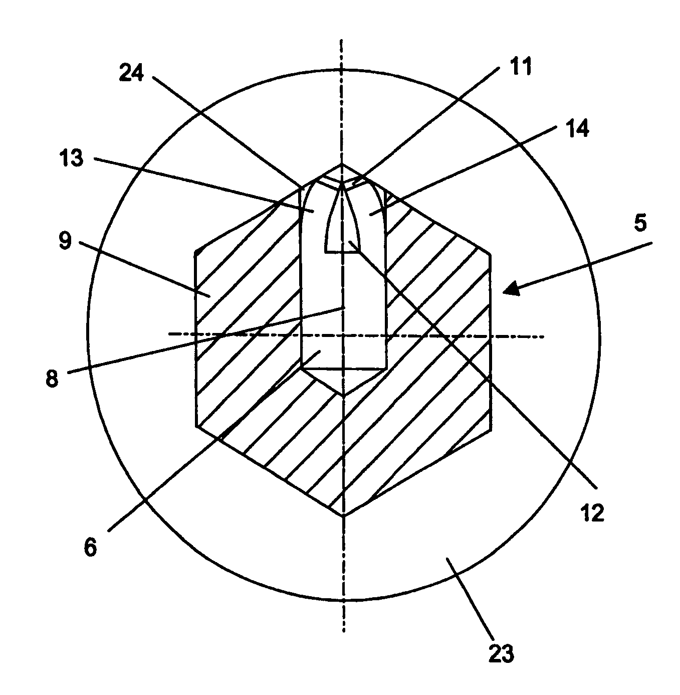
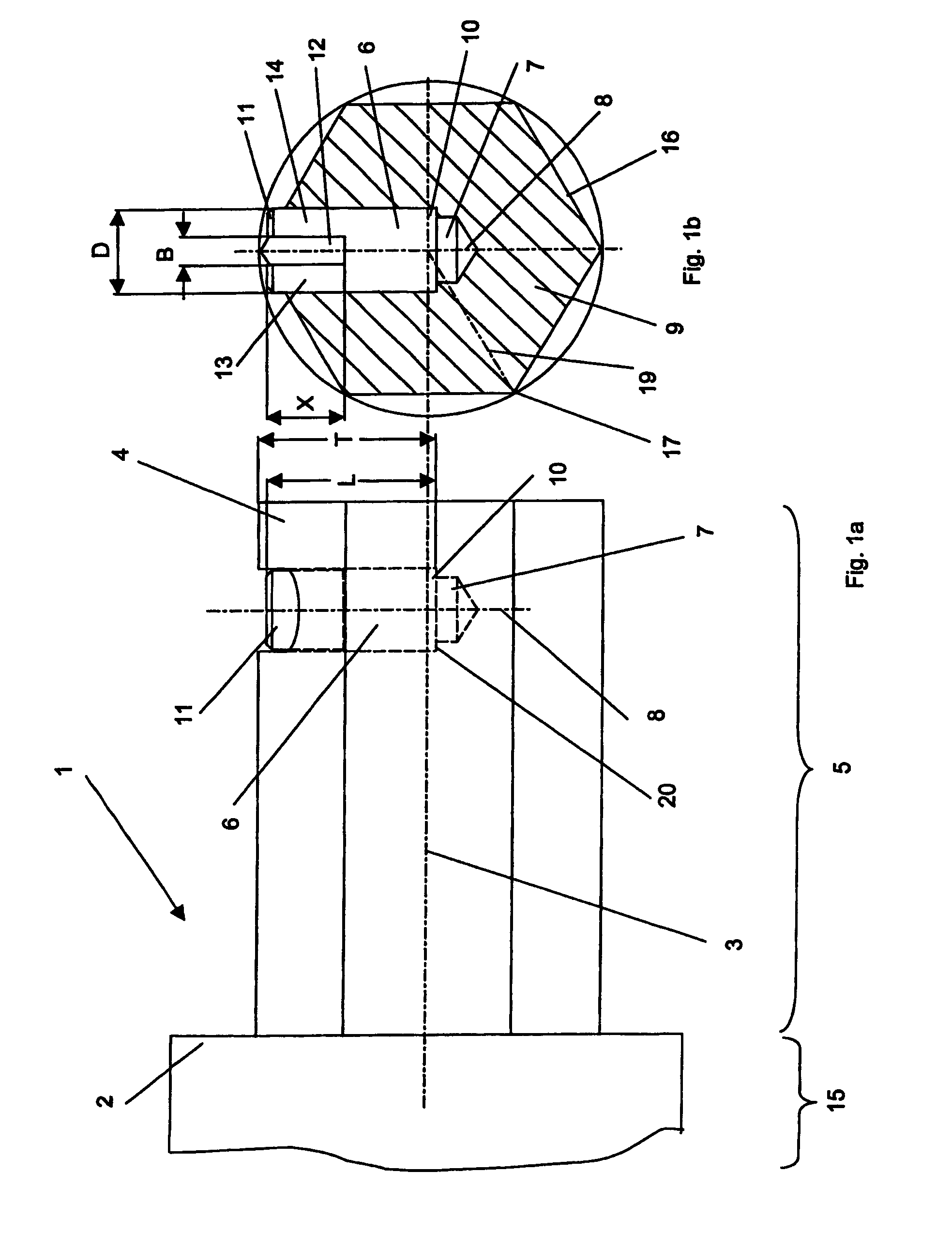
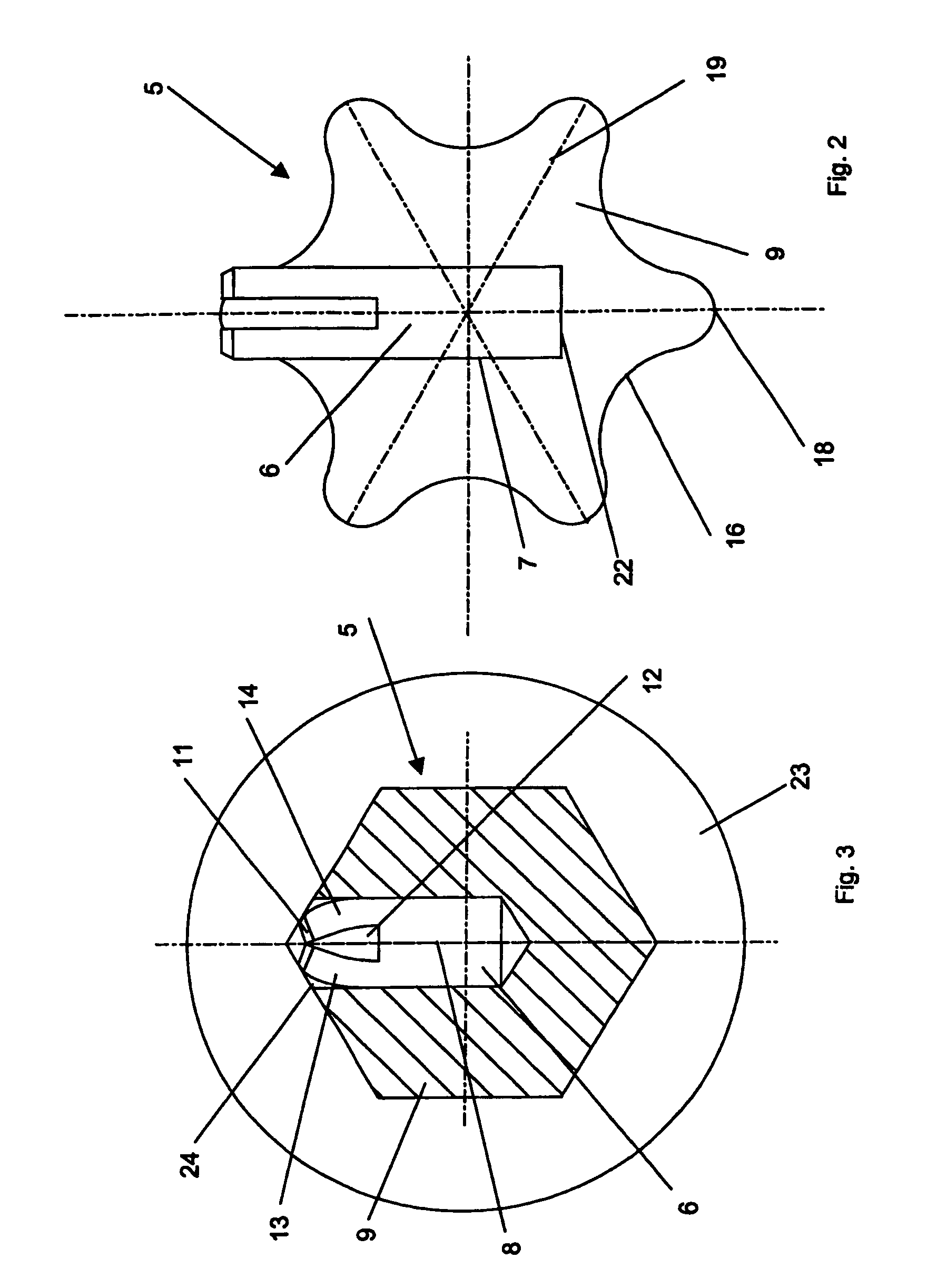
[0027]The screwdriver 1 with screw holder, shown in FIGS. 1a and 1b, comprises essentially a longitudinal shaft 2 with a longitudinal axis 3, a rear segment 15 of the shaft and a front segment 5 of the shaft, and a spring element 6 with a diameter D. The front segment 5 of the shaft has a hexagonal cross-sectional area 9, which is orthogonal to the longitudinal axis 3 and has straight side 16 and corners 17 and can be inserted into a seat at a screw head, which is suitable for screwdrivers. At the front segment 5 of the shaft, the spring element 6 is pressed into a longitudinal recess 7 in the form of a circular borehole with a longitudinal axis 8, which is perpendicular to the longitudinal axis 3. The six corners 17 of the cross sectional area 9 lie on six radii 19, the longitudinal axis 8 coinciding with one of the radii 19. Adjacent to the corners 17, the spring element 6 protrudes over the adjoining side 16. So that the spring element 6 cannot be pressed into the recess 7 as the...


PUM


Abstract

A tool is described comprising a shaft having a first longitudinal axis and a front segment, wherein the front segment has a cross-sectional area, wherein the front segment is configured to engage at least a portion of a screw head, and wherein the front segment has at least a first recess having a second longitudinal axis substantially transverse to the first longitudinal axis; at least one spring element housed in the first recess, wherein a first portion of the spring element at least partially protrudes transversely across the first longitudinal axis; wherein the cross-sectional area is substantially polygonal, having a least one radii; wherein the second longitudinal axis is substantially aligned with at least one radii; and wherein the portion of the spring element protruding transversely across the first longitudinal axis is elastically deformable.

Description

CROSS-REFERENCE TO RELATED APPLICATIONS[0001]This application is a Continuation Application of International Application No. PCT / CH02 / 00322, filed Jun. 13, 2002, the contents of which are expressly incorporated by reference herein.FIELD OF THE INVENTION[0002]The invention relates to a screwdriver with a screw holder, as well as to a spring element for use as a screw holder at a screwdriver.BACKGROUND OF THE INVENTION[0003]So that, during the surgical implantation of an implant, which is to be fastened at a bone, a bone fragment or at a joint of the human or animal body, the surrounding soft parts experience as little damage as possible, it shall be possible to conduct surgery on the bone or, for example, also on a segment of the spinal column without exposing the parts to be treated over a large area (minimal invasive technique). If the openings in the soft parts are very small, non-pointed forceps, for example, are then no longer suitable for introducing bone screws or pedicle scre...

Claims


Application Information

Patent Timeline
Patent Type & Authority Patents(United States)
IPC IPC(8): B25B23/10B25B13/54A61B17/88
CPCA61B17/8875B25B23/108A61B17/8886A61B17/888B25B23/10B25B15/00
Inventor NESSBAUM, FERDINANDCICOIRA, FRANCO
Owner SYNTHES USA
Why Eureka
Try Eureka