Balancer device of engine

a technology of balancer device and engine, which is applied in the direction of machines/engines, mechanical devices, cylinders, etc., can solve the problems of reducing the rigidity of the supporting structure and avoiding uncertain effects

Inactive Publication Date: 2006-03-28
MAZDA MOTOR CORP
View PDF5 Cites 14 Cited by
  • Summary
  • Abstract
  • Description
  • Claims
  • Application Information

AI Technical Summary

Benefits of technology

[0007]The present invention has been devised in view of the above-described problem of an balancer device of an engine including a pair of balancer shafts and a driven sprocket attached to either one of the balancer shafts, and an object of the present invention is to provide a balancer device of an engine that can support the balancer near the driven sprocket firmly and rotatably.

Problems solved by technology

Otherwise, if the second bearing portion is configured of the half-split structure by the upper and lower cases like the first bearing portion, the tension of the endless chain may deteriorate a firm connection of the both cases and thus the supporting rigidity thereof may decrease, resulting in an uncertain avoidance of the above-described problem.

Method used


Image

  • Balancer device of engine
  • Balancer device of engine
  • Balancer device of engine

Examples


Embodiment Construction

[0040]Hereinafter, a preferred embodiment of the present invention will be described with reference to the accompanying drawings.

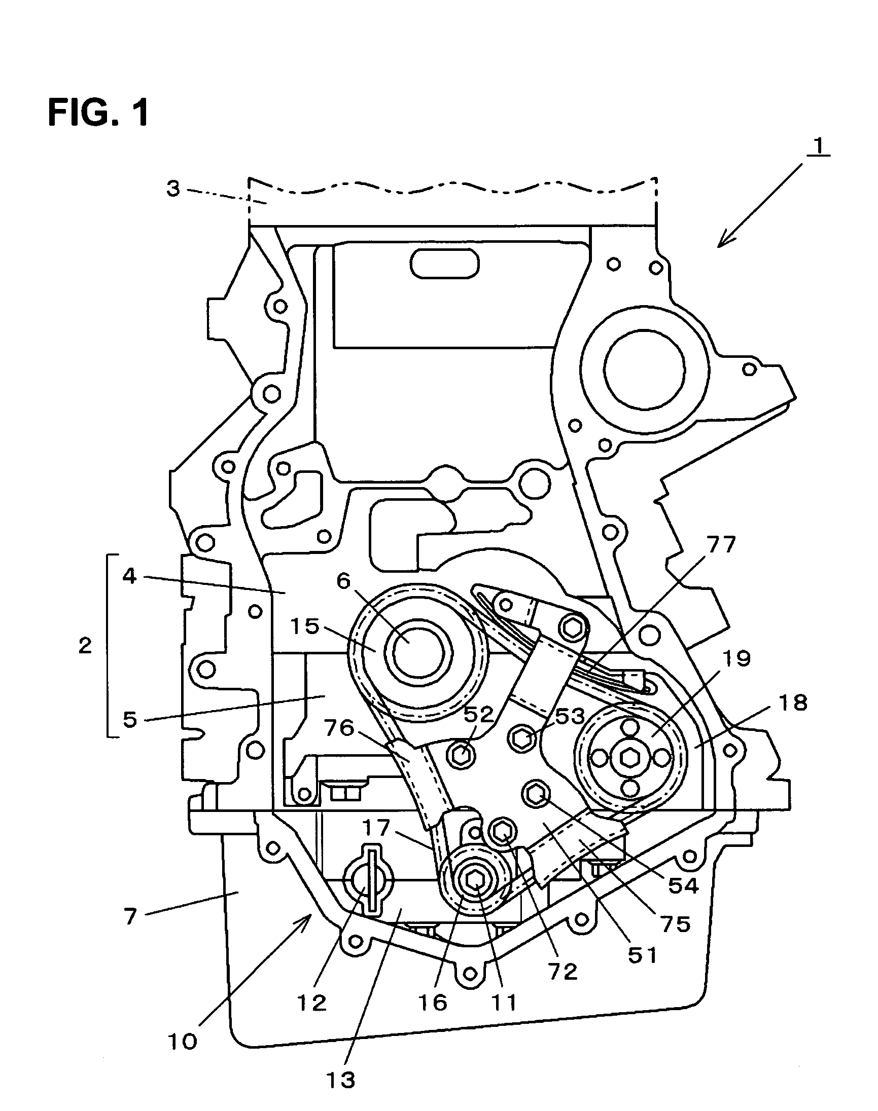
[0041]in the present embodiment, the present invention is applied to an engine 1 shown in FIG. 1. The engine 1 is an inline four-cylinder reciprocating engine. FIG. 1 shows the engine 1, when seen from its front side (a side of a chain cover, but herein not illustrated). An engine block 2 constituting a main body of the engine 1 includes a cylinder block 4 to which a cylinder head 3 is attached and a bearing frame 5 which is attached to a lower portion of the cylinder block 4. The bearing frame 5 is formed in a single piece which integrates plural bearing caps, and supports a crankshaft 6 rotatably in cooperation with the cylinder block 4. Herein, the cylinder block 4 supports an upper half of the crankshaft 6, while the bearing frame 5 supports a lower half of the crankshaft 6. An oil pan 7 for reserving a lubrication oil is attached to a bottom face of t...


PUM


Abstract

A first balancer shaft includes a shaft extension portion extending forward, to which a driven sprocket is attached. A case member includes a first bearing portion supporting the balancer shaft near its weight portions and rotational gear and a second bearing portion supporting the same near its driven sprocket. The case member includes an upper case coupled to a cylinder block and a lower case facing to the upper case, and there is provided a case extension portion extending forward at the upper case. The first bearing portion is configured of a hole formed by half-split portions of the both cases and the second bearing portion is configured of a hole formed integrally at the case extension portion.

Description

BACKGROUND OF THE INVENTION[0001]The present invention relates to a balancer device of an engine and belongs to a technical filed of measures against engine vibration and noise.[0002]Generally, the balancer device equipped at an engine for a motor vehicle and the like for suppressing vibration and noise thereof has a structure in which a pair of balancer shafts having weight portions are disposed in parallel to a crankshaft so as to be supported rotatably at a case member which is provided at a lower portion of an engine block (an assembly of engine parts, such as, for example, a cylinder block, a lower block, a bearing cap, a bearing frame) supporting a crankshaft rotatably. Also, there are provided an endless chain winding around a driving sprocket attached to one end of the crankshaft (for example, to a front end of the engine) and a driven sprocket attached to one end of either of the balancer shafts (first balancer shaft), and a pair rotational gears provided on the both balanc...

Claims


Application Information

Patent Timeline
Patent Type & Authority Patents(United States)
IPC IPC(8): F02B75/06F16F15/26
CPCF16F15/265F02B75/06
Inventor SATO, MASAAKIIMAMURA, SATOSHIHASETO, SAKUMIISAYAMA, KAZUOTANAKA, NOBUHIKONODA, AKIHIROHIROSE, ICHIRO
Owner MAZDA MOTOR CORP
Why Eureka
Try Eureka