Inflating device for tires

a technology for inflating devices and tires, which is applied in the field of inflating devices for tires, can solve the problems of air seeping through the gap, air flow, and heavy truck tires, and achieve the effects of reducing kickback of means, convenient storage, and facilitating selective positioning of means

Inactive Publication Date: 2006-03-28
BRAHLER II RICHARD W
View PDF12 Cites 15 Cited by
  • Summary
  • Abstract
  • Description
  • Claims
  • Application Information

AI Technical Summary

Benefits of technology

[0013]In an alternative embodiment, a positioning member is provided to releasably retain the means for directing the pressurized air between the tubeless tire and rim for convenient storage. The positioning member also facilitates selective positioning of the means for directing the pressurized air between the tubeless tire and rim during seating. In operation, the positioning member reduces kickback of the means for directing the pressurized air between the tubeless tire and rim during seating. The positioning member also allows the operator to use one or possibly no hands on the means for directing the pressurized air between the tubeless tire and rim during seating.
[0027]It is another object of the present invention to provide a positioning member which allows the operator to use one or possibly no hands on the means for directing the pressurized air between the tubeless tire and rim during seating.

Problems solved by technology

As shown in the prior art, one of the difficulties presented in changing tubeless tires is establishing the initial airtight seal between the beads of the tire and the bead-seating surfaces of the rim on which it is to be mounted.
An uninflated tire has an open space or gap between the bead and the bead-seating surface of the rim, which is often so large that air seeps through the gap during inflation.
Heavy truck tires especially encounter this problem because the stiffness of the tires prevents sufficient reduction of the gap for seating to occur.
However, this device fails to recognize that its discharge nozzle restricts airflow and the valve used to discharge the air flow reduces the effectiveness of the apparatus because it retards the rise time of the pulse of air.
However, this apparatus contemplates use of a rim support block, which is independent of the device and therefore must be hauled along with the device.
Although this device provides for increased pressure rise time, it is susceptible to small air leaks, has an appreciable kickback, is expensive to manufacture, and does not contemplate supporting the rim on the tire prior to actuating the device.
However, the quick fill / release port is susceptible to leakage and will discharge the air tank completely within an hour or so.
This makes the device unsuitable for use over an extended period of time.
For example, tow truck operators that have to travel an extended amount of time or a trucker who wishes to travel with the device over an extended haul will find this device unsuitable for use.
Additionally, this device does not contemplate supporting the rim on the tire prior to actuating the device.

Method used


Image

  • Inflating device for tires
  • Inflating device for tires
  • Inflating device for tires

Examples


Embodiment Construction

[0046]While the invention may be susceptible to embodiments in different forms, there will be described in detail the preferred embodiment and alternative embodiments with the understanding that the present disclosure is to be considered an exemplification of the principles of the invention, and is not intended to limit the claims to that which is described herein.

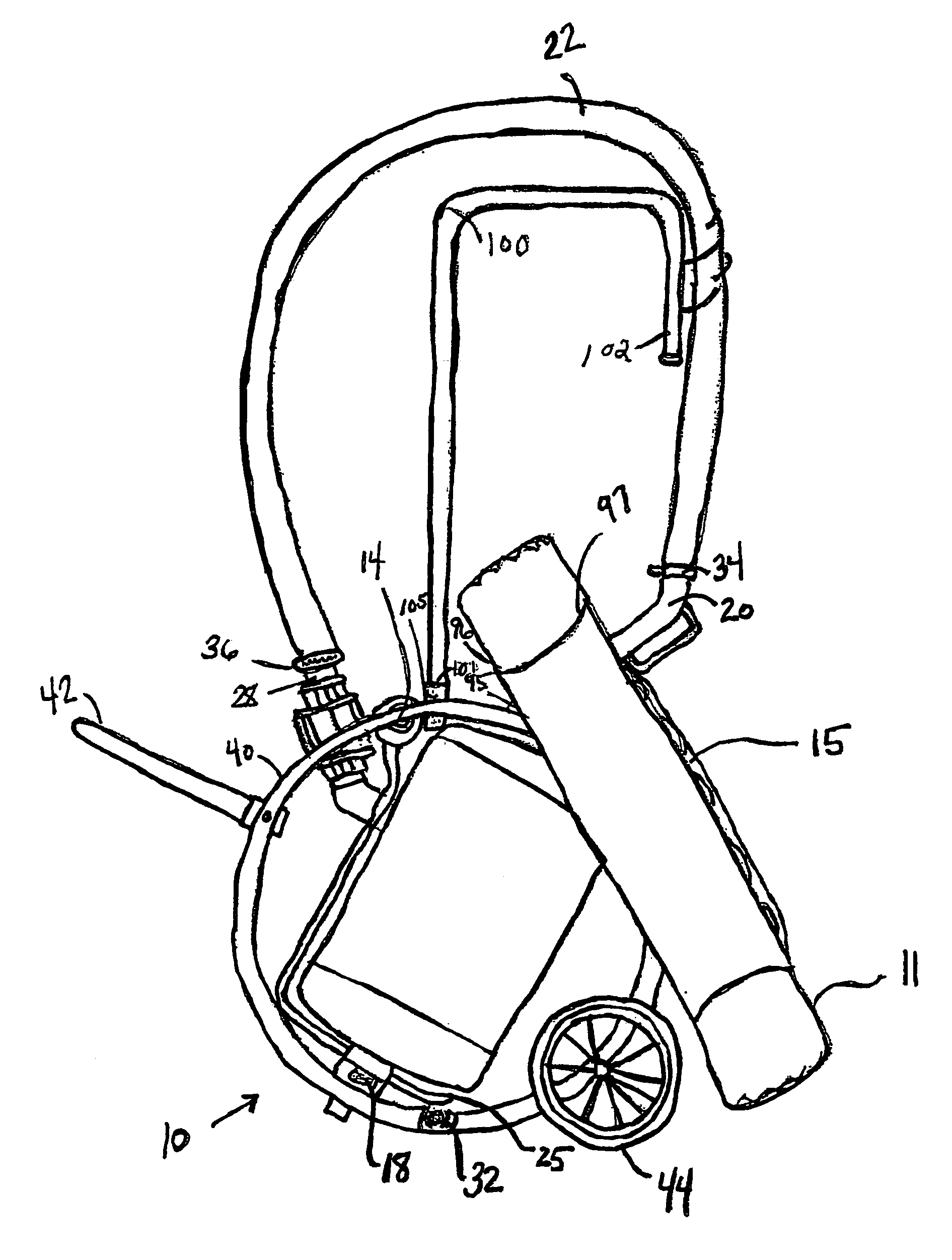
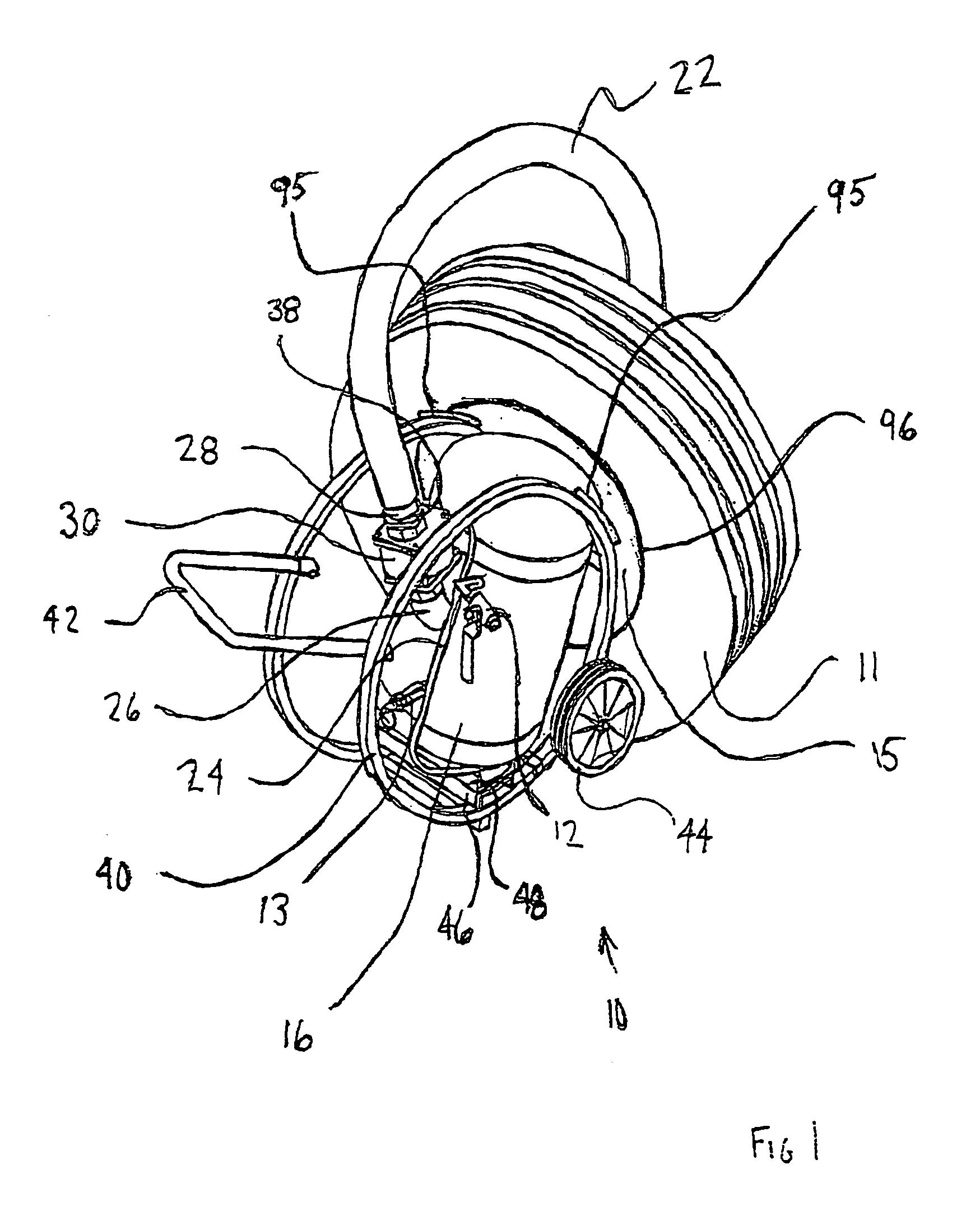
[0047]FIG. 1 is an elevated view of the device 10 of the preferred embodiment in association with a tire 11 and rim 15. The device 10 has an air tank 16, which is preferably an eight gallon tank. In the preferred embodiment, the air tank 16 is ASME® and CE® approved. The air tank 16 has affixed an intank valve 12, which is preferably a ¼ inch ball valve. The intank valve 12 allows for pressurization of the air tank 16, preferably to 120 pounds per square inch (lbs. / in2). This preferred feature provides for a safer working environment because of the lower working pressures utilized, as compared to those devices known in the...


PUM


Abstract

A portable device for seating the beads of a tubeless tire and rim assembly, the device including an air tank containing pressurized air, the air tank being mounted substantially within a bracket, the bracket having a surface for supportably receiving the tire and rim assembly, a means for directing the pressurized air between a bead of the tire and the rim, and a positioning member which selectively stores the means for directing the pressurized air between a bead of the tire and the rim during seating.

Description

PRIORITY[0001]This is a continuation-in-part of application Ser. No. 10 / 701,093 filed Nov. 4, 2003 claiming priority of provisional patent application Ser. No. 60 / 423,493 filed Nov. 4, 2002.BACKGROUND OF THE INVENTION[0002]1. Field of the Invention[0003]The present invention relates to the field of seating the beads of a tubeless tire to a rim.[0004]2. The Prior Art[0005]The present invention relates to an improved apparatus for creating an airtight seal between the beads of a tubeless tire and a rim. The present invention is directed to an apparatus that generates a pneumatic pulse and directs the pulse in a manner to impart momentum to a bead and inject air into the tire, thereby setting a bead of a tubeless tire to a rim.[0006]As shown in the prior art, one of the difficulties presented in changing tubeless tires is establishing the initial airtight seal between the beads of the tire and the bead-seating surfaces of the rim on which it is to be mounted. An uninflated tire has an ...

Claims


Application Information

Patent Timeline
Patent Type & Authority Patents(United States)
IPC IPC(8): B60C25/132B60C25/14
CPCB60C25/145
Inventor BRAHLER, II, RICHARD W.
Owner BRAHLER II RICHARD W
Why Eureka
Try Eureka