Apparatus and method for expanding and fixing a tubular member within another tubular member, a liner or a borehole

a tubular member and tubular member technology, applied in the direction of drilling casings, well accessories, drilling pipes, etc., can solve the problems of reducing the service life of the packer, so as to facilitate the engagement and increase the resistance to lateral movement.

Inactive Publication Date: 2006-03-28
SCHLUMBERGER TECH CORP +1
View PDF14 Cites 65 Cited by
  • Summary
  • Abstract
  • Description
  • Claims
  • Application Information

AI Technical Summary

Benefits of technology

[0024]The tubular member is typically moved radially outwardly by the pressure to bear against the inner surface of the liner or borehole wall. Optionally, the liner may be provided with a surface that facilitates providing engagement between the liner and the tubular member, and the surface may comprise one or more recesses. This has the advantage of increasing the resistance to lateral movement occurring between the liner and the tubular member preventing the tubular member from being pushed down or pulled out of the liner or borehole.

Problems solved by technology

Today, even more well environments have high temperature and pressure, and it is a challenge to develop reliable equipment for such environments.
The prior art have some disadvantages, for example the high temperature and high pressure can cause extruding of the packer.
Consequently, this may result in a leakage.
Another disadvantage is that some packers after compression in well bores with extreme temperatures and pressures will not function properly, for example the relaxation of the packer can work poorly.
Consequently, this requires considerable forces to be applied, which again demand packers with special properties.

Method used


Image

  • Apparatus and method for expanding and fixing a tubular member within another tubular member, a liner or a borehole
  • Apparatus and method for expanding and fixing a tubular member within another tubular member, a liner or a borehole
  • Apparatus and method for expanding and fixing a tubular member within another tubular member, a liner or a borehole

Examples


third embodiment

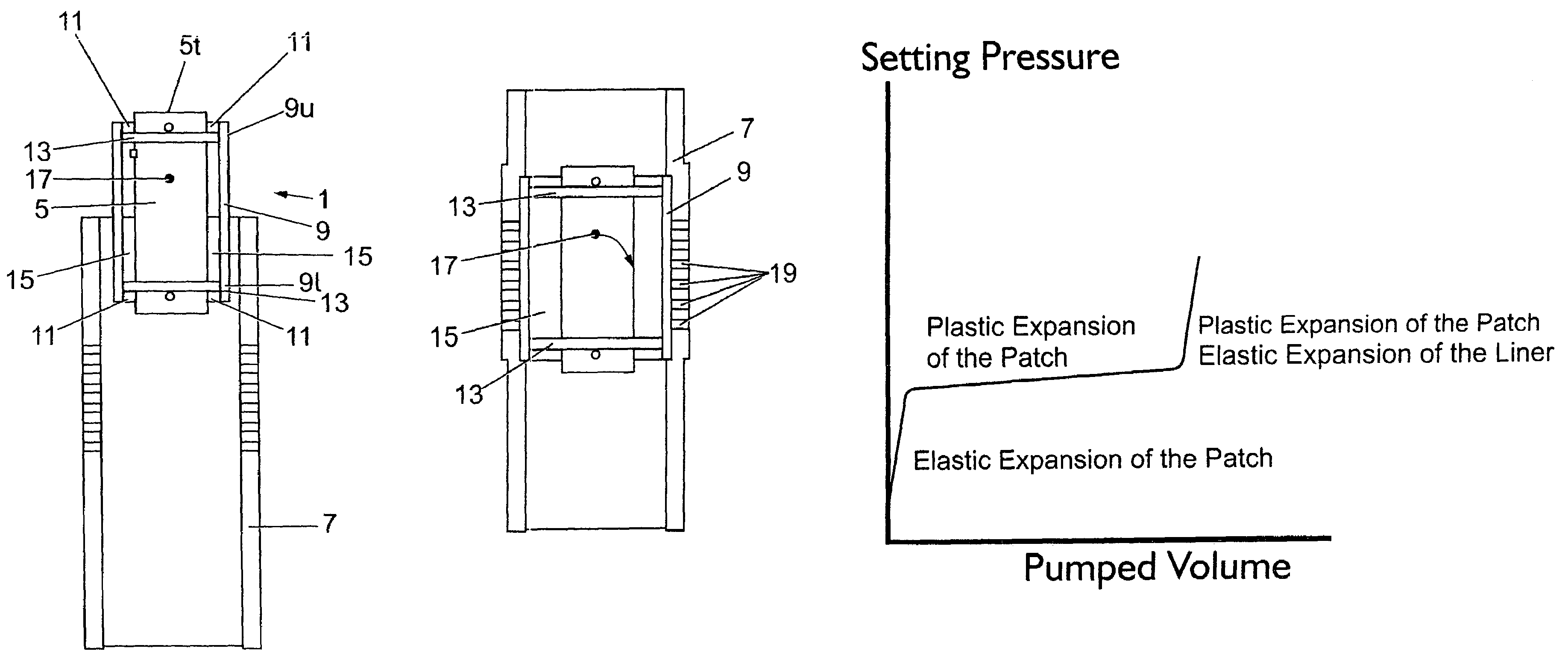
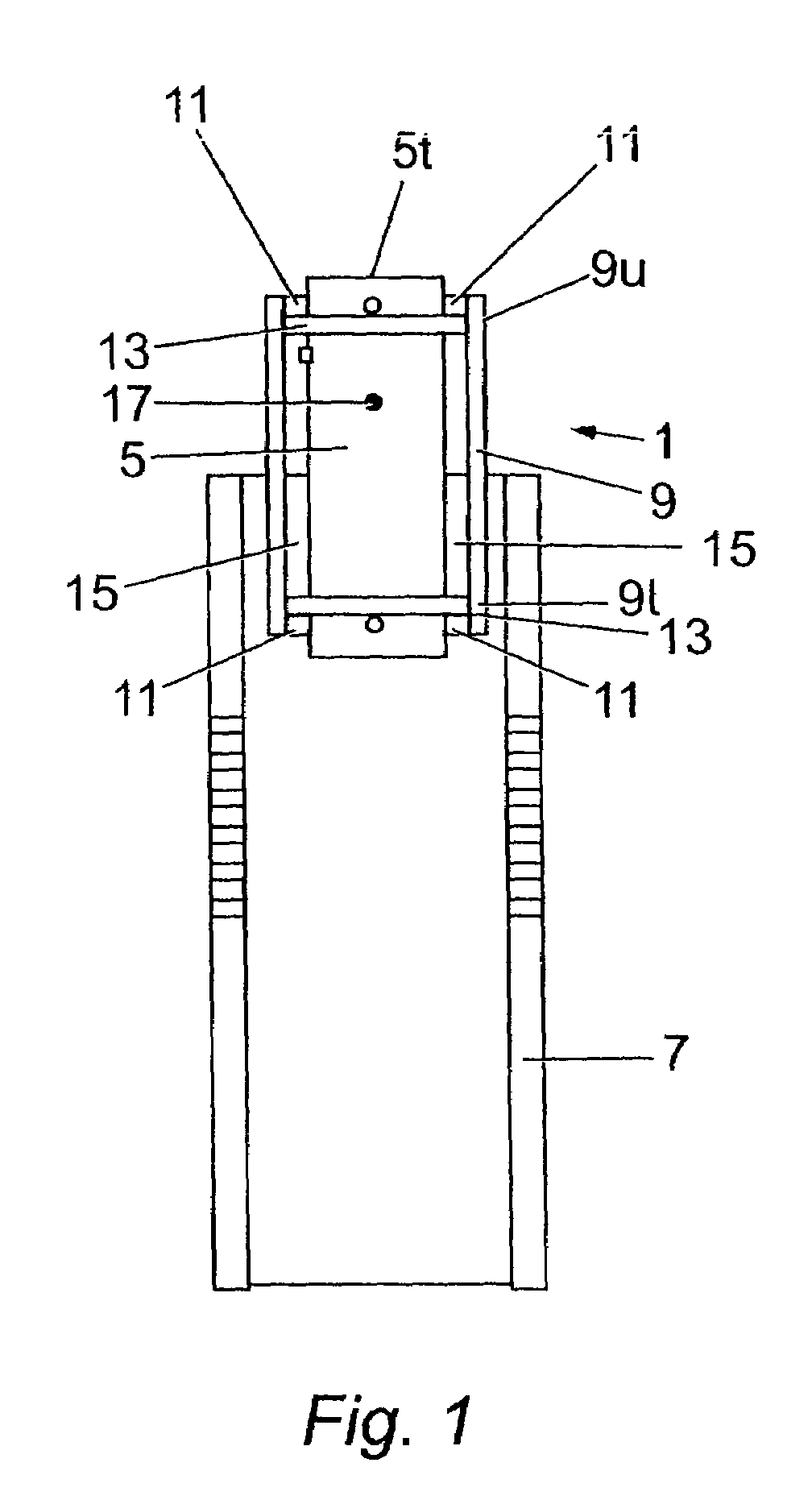
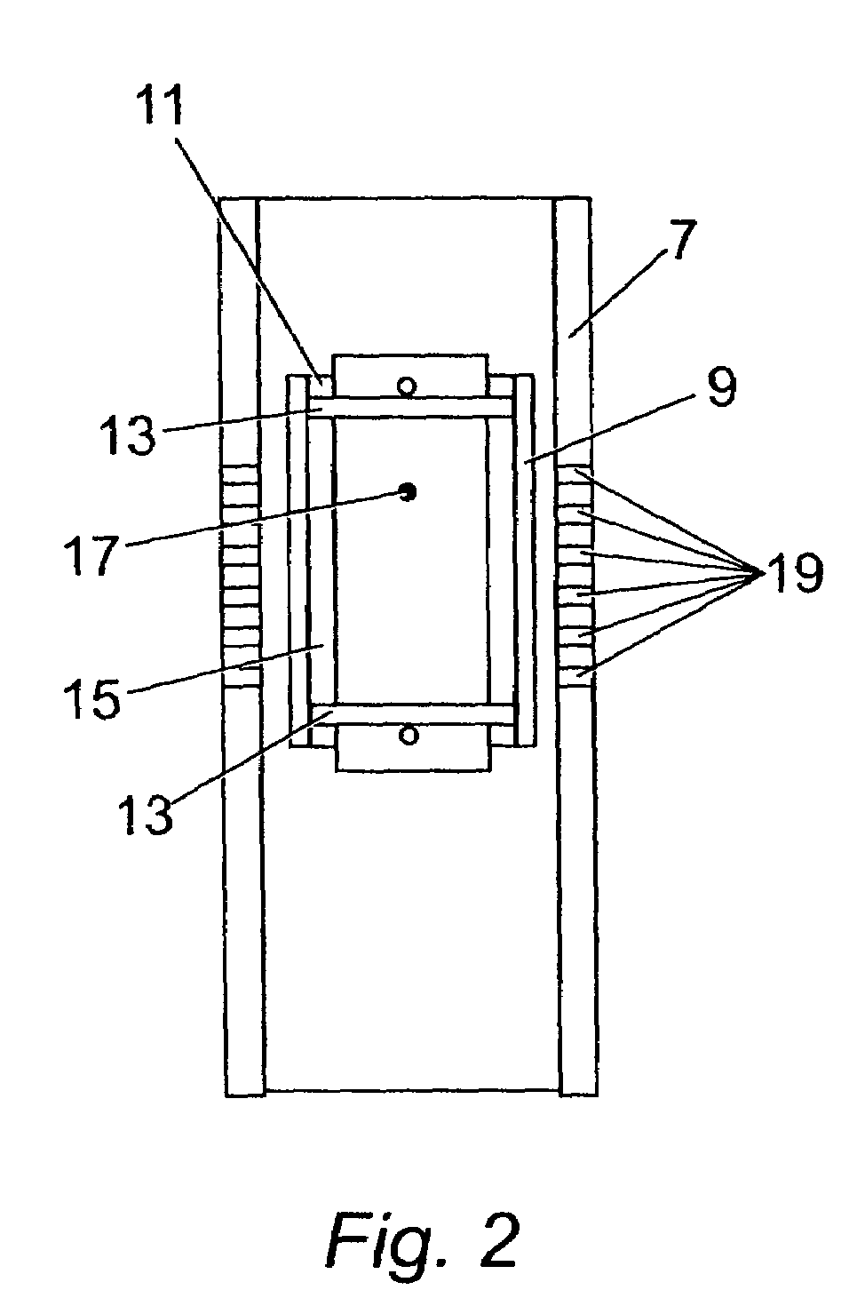
[0106]an apparatus in accordance with the present invention is shown in FIG. 13 as comprising a body 5 with upper and lower packer elements 13 and upper and lower sets of hydraulically actuated centralising pins 11. The body also carries a port 17 located between the two packer elements 13 and is operated in a similar manner to the apparatus 1. However, the tubular member 9 is integrally formed with a seal assy 25 at its lower end, which can be used as a tubing receptacle and seal assembly. It should be noted in FIG. 13 that the liner 7 has been pre-formed with a bank of recesses 27 which are axially spaced along a short length of the interior surface of the liner 7. In the examples shown in FIG. 13, there are four recesses 27, but any suitable number of recesses 27 can be performed. As seen most clearly in FIG. 14b, the tubular member 9 will expand into the recesses 27, and the engagement there between will provide the tubular member 9 with a much higher resistance to lateral movem...

first embodiment

[0112]Therefore, it can be seen that the apparatus 1 can be provided with an uninterrupted central mandrel section which couples to both the upper and lower ends of the tubular member 9, such as the one piece body section 5 of the first embodiment shown in FIG. 1, or can be provided with split upper 21 and lower 23 body sections which are respectively coupled to the upper and lower ends of the tubular member 9, such as the embodiment shown in FIG. 12. In the latter scenario, the opposing forces on the seals 13 are contained by, for instance slips (as indicated for the top seal 13), or a no go (as indicated for the bottom seal 13). Also, the length of the tubular member 9 is variable, depending upon conveyance technique, well geometry etc.

[0113]The expansion of the tubular member 9 against the inner surface of the liner 7 may provide a high integrity hydraulic fluid and / or gas seal therebetween, and this will particularly be the case when the tubular member 9 is expanded into recesse...


PUM


Abstract

An apparatus for securing a tubular member within a liner or borehole has a seal means connected within the tubular member, and a pressure control device operable to increase the pressure within the tubular member, such that operation of the pressure control means causes the tubular member to move radially outwardly to bear against the inner surface of the liner or borehole wall. Also, a packer for use in a downhole annular space and an isolation plug for plugging a downhole tubular are disclosed.

Description

FIELD OF THE INVENTION[0001]The present invention relates to an apparatus and method, particularly but not exclusively, for deploying and / or securing a tubular section referred to as a “tubular member” within a liner or borehole.BACKGROUND OF THE INVENTION[0002]Oil or gas wells are conventionally drilled with a drill string at which point the open hole is not lined, hereinafter referred to as a “borehole”. After drilling, the oil, water or gas well is typically completed thereafter with a casing or liner and a production tubing, all of which from here on are referred to as a “liner”.[0003]Conventionally, during the drilling, production or workover phase of an oil, water or gas well, and from a first aspect of the present invention, there may be a requirement to provide a patch or temporary casing across an interval, such as a damaged section of liner, or an open hole section of the borehole.[0004]Additionally, and from a second aspect of the present invention, there may be a require...

Claims


Application Information

Patent Timeline
Patent Type & Authority Patents(United States)
IPC IPC(8): E21B23/02E21B33/124E21B29/10E21B33/10E21B43/10
CPCE21B29/10E21B43/105E21B43/103E21B33/10E21B23/06E21B33/12E21B33/128E21B33/1285E21B33/13E21B43/10E21B17/02E21B33/00E21B33/1216E21B29/00
Inventor HAZEL, PAUL RODERICKHIORTH, ESPEN
Owner SCHLUMBERGER TECH CORP
Why Eureka
Try Eureka