System and method for accurate reading of rotating disk

a technology of rotating disks and reading systems, applied in the direction of discharge tubes/lamp details, instruments, sustainable buildings, etc., can solve the problems of inability to provide, in a cost effective manner, numerous additional functions currently being demanded, and the use of fully electronic meters is generally deemed cost prohibitive, so as to facilitate the “readability” of tapes, the effect of accurately determining the rotational direction of the disks

Inactive Publication Date: 2006-03-28
LANDISGYR TECH
View PDF8 Cites 179 Cited by
  • Summary
  • Abstract
  • Description
  • Claims
  • Application Information

AI Technical Summary

Benefits of technology

[0013]Briefly described, in architecture, the system can be implemented as follows. The present invention utilizes a reflective tape affixed to the rotating disk of a utility meter. This reflective tape is constructed so as to have sections of highly reflective material and non-reflective material, separated by clearly defined edges. Thus, the difference between the reflective areas and the non-reflective areas provides a high degree of contrast and facilitates the “readability” of the tape. As the disk rotates with the use of electricity, the tape is “read” by an optical sensor that is connected to a circuit card. The circuit card is retrofittably mounted in available space within the utility meter so that the optical sensor aligns with the tape as it is carried through its revolutions. By “reading” the passage of the reflective and non-reflective sections of the tape, the consumption of electricity and the rotational direction of the disk can be accurately determined. The consumption data is then communicated to the circuit card and then transmitted to the utility company.

Problems solved by technology

These electromechanical meters are generally effective in metering electrical energy consumption, but are incapable of providing, in a cost effective manner, numerous additional functions currently being demanded by the utility industry.
While such meters may be highly desirable for new installations, replacing existing meters with new, fully electronic meters is generally deemed cost prohibitive.
There are, however, various problems and shortcomings with the methodologies employed in the past.
Although each of the aforementioned methods of remotely collecting utility consumption data is convenient and efficient for the utility companies, it does not address the concern of the accuracy of the readings and the detection of tampering with the utility meter.
First, it is often difficult to obtain accurate and reliable readings. Although the disk is silver in color, it does not always provide a good reflectivity. Consequently, the contrast between the black stripe and disk may not be as “electrically readable” as desired. Empirical tests have shown that, on a three volt scale, often only a 0.8 volt difference is measured between readings of the black stripe and the silver disk. These readings are further compromised by the fact that the paint or marker typically fades over time, and that good / definable edges are often not present on the black stripe. Faded color and poorly defined edges lead to misreadings and, therefore, inaccuracy in the remote reading system.
A second shortcoming of this type of system is its failure to determine when the disk is not moving or when the disk is rotating in a reverse direction.
Theft of electricity has increased in recent years, and many consumers have discovered ways to bypass electrical meters or otherwise cause the disk to stop rotating for extended periods of time.
With the marking or painting system it is difficult, if not impossible, to detect and prevent these and other types of electricity theft.
However, the invention of Johnson is not easily retrofitted to existing utility meters and requires extensive circuitry and software support in order to adequately perform its tamper detection and electricity consumption monitoring functions.
However, the Moore adapter module device requires substantial space to mount the device to a utility meter and additionally requires direct linkage to the original meter's dials and a plurality of other moving parts in order to monitor electricity consumption.
Furthermore, because the Moore device is retrofitted to the outside of the existing utility meter it is more prone to tampering.

Method used


Image

  • System and method for accurate reading of rotating disk
  • System and method for accurate reading of rotating disk
  • System and method for accurate reading of rotating disk

Examples


Embodiment Construction

[0024]Having summarized the invention above, reference is now made in detail to the description of the invention as illustrated in the drawings. While the invention will be described in connection with these drawings, there is no intent to limit it to the embodiment or embodiments disclosed therein. On the contrary, the intent is to cover all alternatives, modifications and equivalents included within the spirit and scope of the invention as defined by the appended claims.

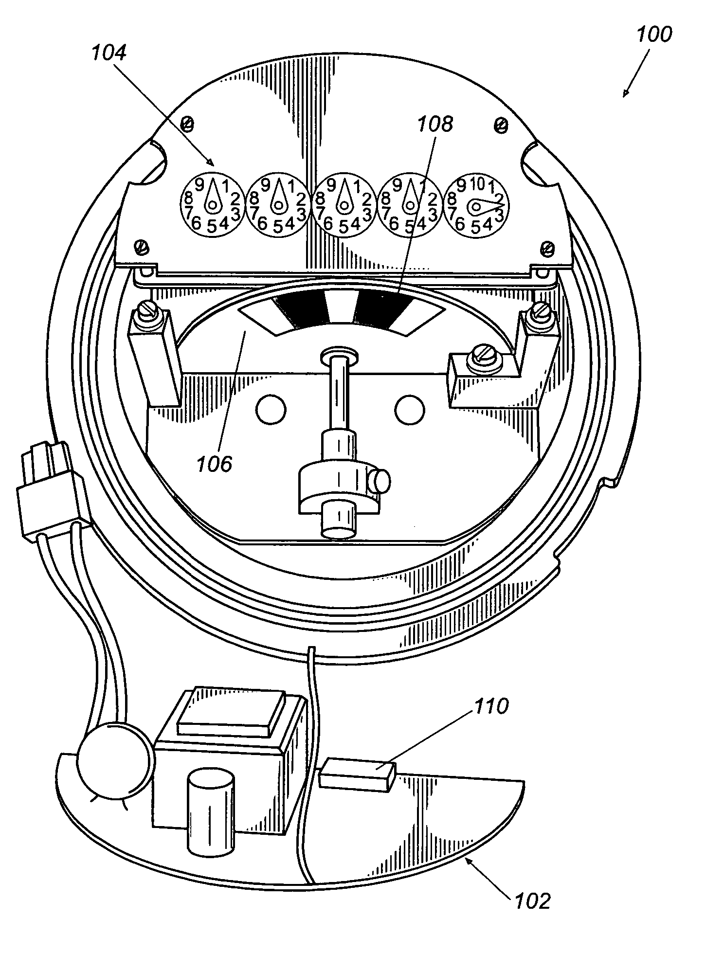
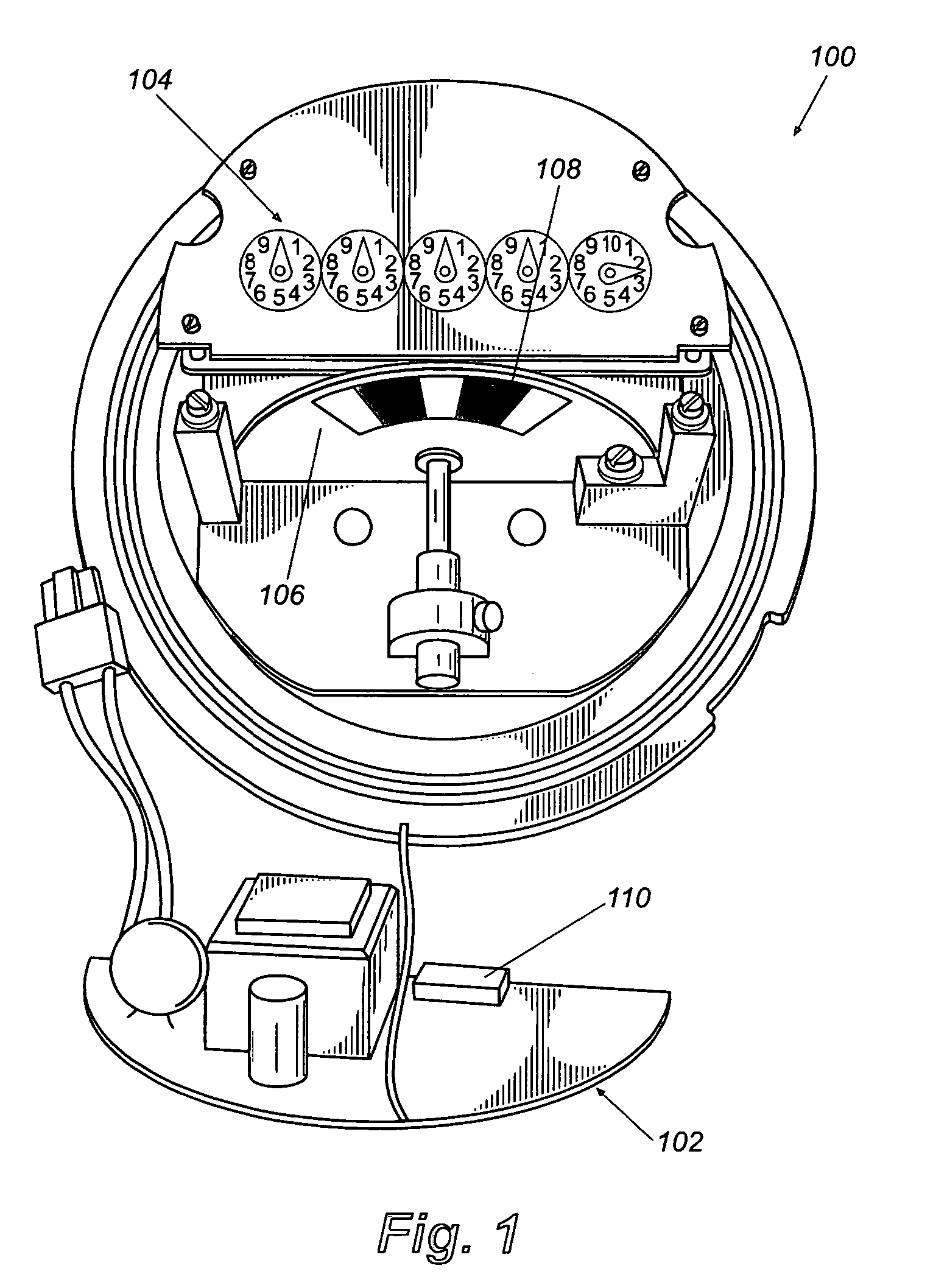
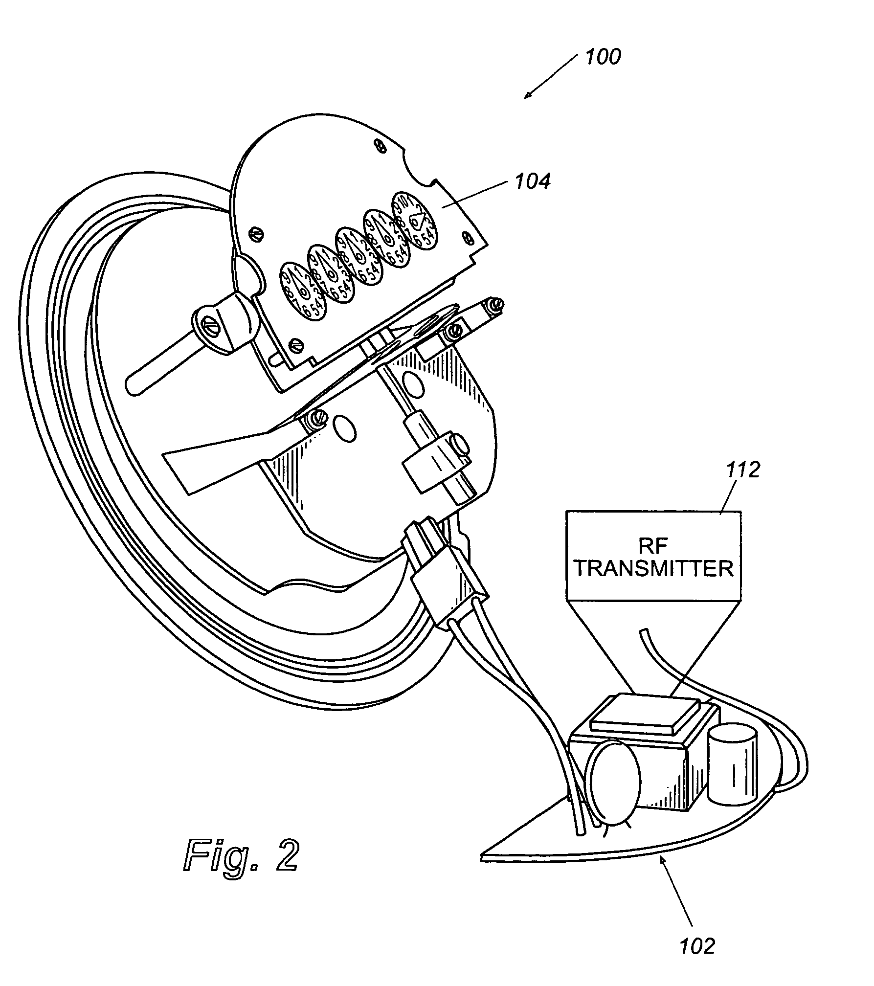
[0025]Reference is now made to FIGS. 1 and 2, which are a front view and side view, respectively, of a utility meter 100 showing a circuit card 102, constructed in accordance with the invention, exploded therefrom. The meter 100 includes an “index”104 comprising five dials, which collectively, provide a visual indication of the current reading for the utility meter. In addition to the index 104, the utility meter 100 includes a rotating disk 106 that rotates at a speed that is proportional to the instantaneous elec...


PUM


Abstract

A novel system and method for achieving accurate readings of the rotational speed, number of revolutions and direction of rotation of a utility system. More specifically, a system and method for retrofitting existing utility meters with a lightweight tape, having contrasting sections of reflective and non-reflective material applied thereto, which is read by optical sensors as the lightweight tape passes by with the revolutions of the disk of the utility meter. Additionally, the system and method detects unauthorized use of the utility or tampering with the utility meter and its functions.

Description

CROSS-REFERENCE TO RELATED APPLICATION[0001]This application is a continuation of U.S. Patent Application entitled, “System and Method for Accurate Reading of Rotating Disk,” having Ser. No. 09 / 956,377, filed Sep. 19, 2001, now U.S. Pat. No. 6,784,807 which is entirely incorporated herein by reference. This application also claims benefit of Provisional application Ser. No. 60 / 267,736 filed on Feb. 9, 2001.TECHNICAL FIELD[0002]The present invention generally relates to obtaining accurate readings of a moving device, such as a rotating disk. The present invention more particularly relates to obtaining an accurate remote reading of a rotating disk of a utility meter and detecting and preventing tampering and theft of utilities.BACKGROUND OF THE INVENTION[0003]Electrical metering of residential energy has historically been accomplished using electromechanical meters that sense electromagnetic fields in proximity to voltage coils and current carrying conductors. These electromechanical ...

Claims


Application Information

Patent Timeline
Patent Type & Authority Patents(United States)
IPC IPC(8): G08C19/38G01D4/00G08C17/02
CPCG01D4/008G08C17/02Y04S20/50Y02B90/247Y02B90/20Y04S20/30
Inventor PETITE, THOMAS D.HUFF, RICHARD M.DAVIS, JAMES
Owner LANDISGYR TECH
Why Eureka
Try Eureka