Transferring apparatus with two or more voltage output modes

a technology of voltage output mode and transfer apparatus, which is applied in the direction of electrographic process apparatus, applications, instruments, etc., can solve the problems of contamination of the transfer roller with toner, and achieve the effect of improving the image forming apparatus

Active Publication Date: 2006-03-28
CANON KK
View PDF11 Cites 7 Cited by
  • Summary
  • Abstract
  • Description
  • Claims
  • Application Information

AI Technical Summary

Benefits of technology

[0024]Further, another object of the present invention is to provide a transferring apparatus including:

Problems solved by technology

The sheet therefore remains within the apparatus, and the transfer roller may be contaminated by the toner when the sheet is removed manually, or the like.

Method used


Image

  • Transferring apparatus with two or more voltage output modes
  • Transferring apparatus with two or more voltage output modes
  • Transferring apparatus with two or more voltage output modes

Examples


first embodiment

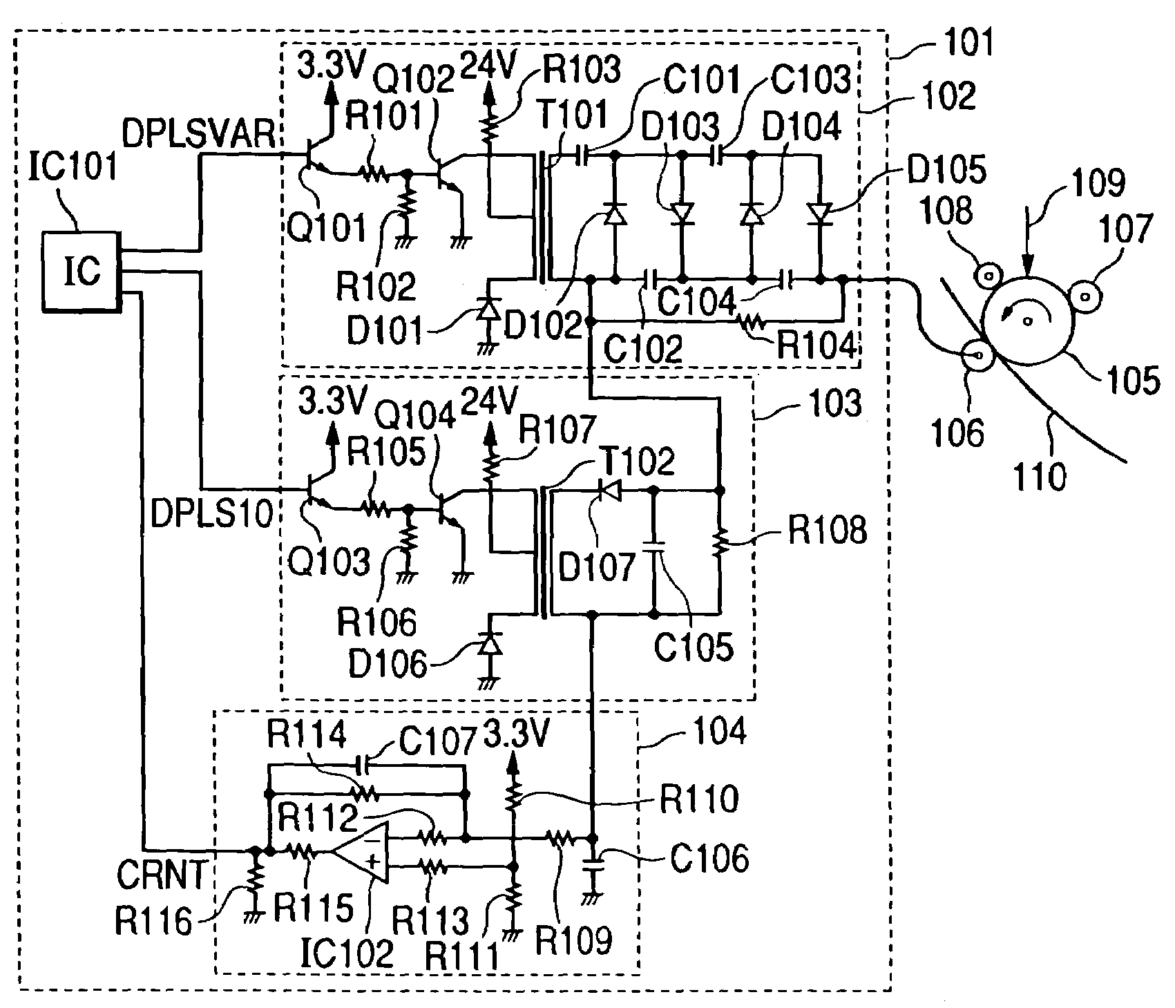
[0043]FIG. 1 is a circuit diagram that shows a configuration of a main portion of a transferring apparatus according to a first embodiment of the present invention. The circuit disclosed in Japanese Patent Application Laid-Open No. H08-140351 is used as a positive transfer voltage generator circuit in this embodiment. Elements within FIG. 1 that are identical to the circuits, components, and members shown in FIG. 9 are identified by the same reference characters as those used in FIG. 9.

[0044]A photosensitive drum 105 that is scanned and exposed by a laser light 109 is provided in an image forming apparatus as shown in FIG. 1, and the photosensitive drum 105 is grounded. A charging roller 107, a developing sleeve 108, and a transfer roller 106 are disposed in the periphery of the photosensitive drum 105. Predetermined voltages are applied to the charging roller 107 and to the developing sleeve 108 by a charging voltage generator circuit (not shown) and a developing voltage generator ...

second embodiment

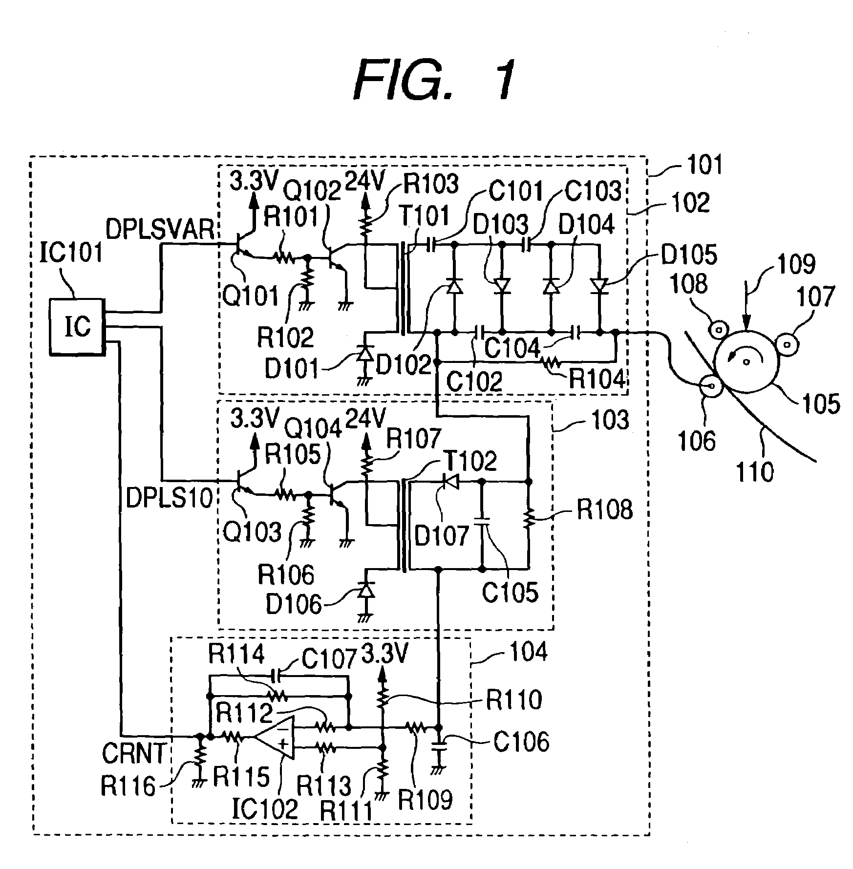
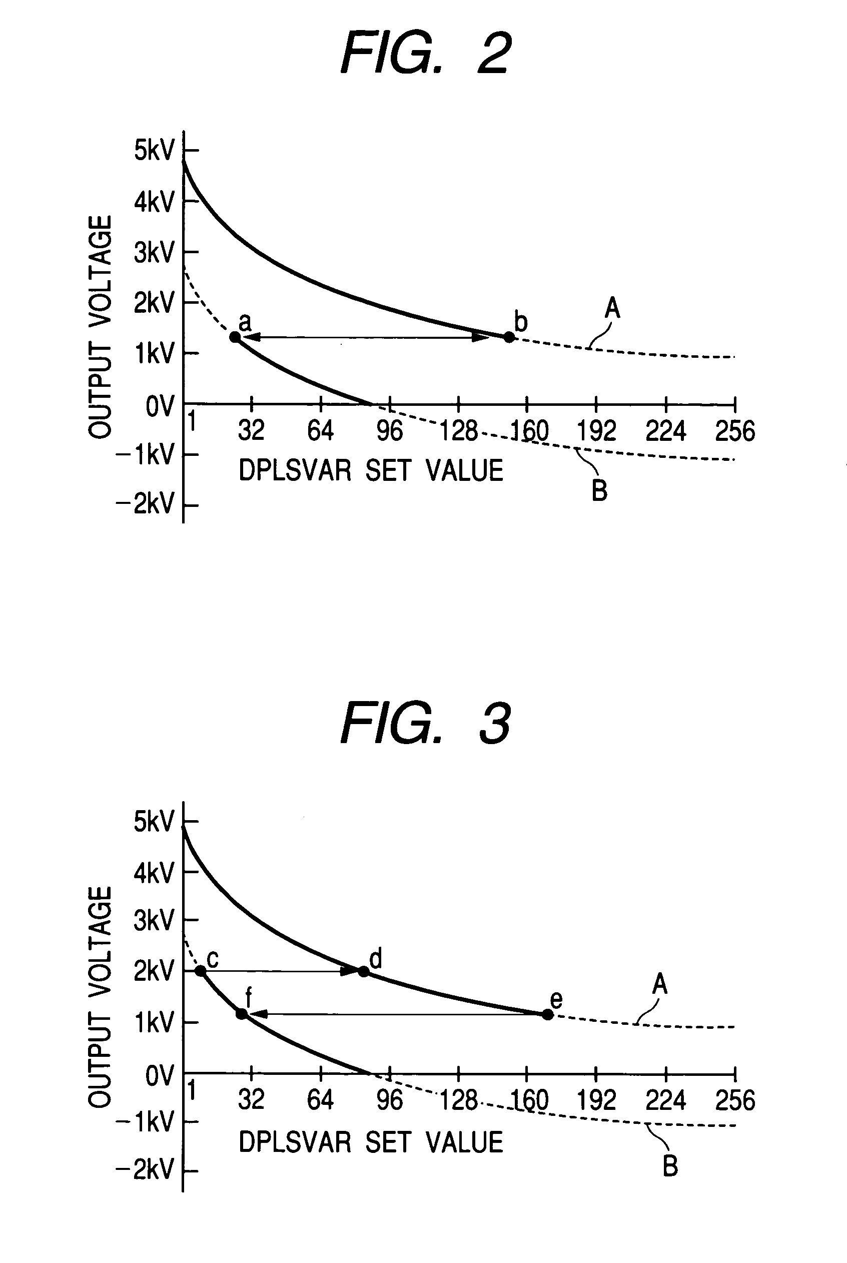
[0066]A second embodiment of the present invention is explained next while referring to FIGS. 4 and 5. FIG. 4 is a diagram that shows a relationship between an output voltage of the negative transfer voltage generator circuit 103, and the frequency (DPLSVAR set value) of the pulse output from the port DPLSVAR of the microcomputer IC101, when there is variation in the output voltage in a transferring apparatus according to the second embodiment of the present invention. FIG. 5 is a diagram that shows a relationship between the output voltage and the frequency (DPLSVAR set value) of the pulse output from the microcomputer IC101 when there is load variation in the transferring apparatus according to the second embodiment of the present invention.

[0067]A case of controlling the transfer voltage by constant current control is explained in the first embodiment described above. a DPLSVAR set value at which the voltage output during the low mode becomes 0 V is very important for systems in ...


PUM


Abstract

To provide a transferring apparatus, it is possible to perform switching between a high mode and a low mode in a transfer voltage generator circuit of a transferring apparatus by using a microcomputer. The high mode is a mode in which a positive transfer voltage generator circuit is operated independently, and a voltage generated by the positive transfer voltage generator circuit is output as a transfer voltage. The low mode is a mode in which the positive transfer voltage generator circuit and a negative transfer voltage generator circuit are both operated, and the voltages generated by each of the circuits are superimposed and output as the transfer voltage.

Description

BACKGROUND OF THE INVENTION[0001]1. Field of the Invention[0002]The present invention relates to a transferring apparatus that is used in an image forming apparatus.[0003]2. Related Background Art[0004]A transferring apparatus is used in an image forming apparatus according to an electrophotographic process in order to transfer a toner image borne on an image bearing member, a so-called photosensitive drum, to a transferring material, a so-called sheet. There are several types of apparatuses known as transferring apparatuses.[0005]Among the transferring apparatuses, a system is widely used for transferring a toner image borne on a photosensitive drum to a sheet by applying a transfer voltage to a cylindrical transferring member, a so-called transfer roller, and passing a sheet between the transfer roller and the photosensitive drum. The transfer roller and the photosensitive drum are in contact in this system in a state in which a sheet has not passed between the transfer roller and...

Claims


Application Information

Patent Timeline
Patent Type & Authority Patents(United States)
IPC IPC(8): G03G15/16G03G21/00G03G13/16G03G15/14
CPCG03G15/1675A47J37/067A47J43/07
Inventor NAKATA, YASUHIRONAKAHARA, HISASHI
Owner CANON KK
Why Eureka
Try Eureka