Vacuum suction apparatus

a vacuum suction and suction tube technology, applied in the direction of machine supports, building scaffolds, other domestic objects, etc., can solve the problems of gradual loss of elasticity and suction strength, clippers not fitting on all automobiles, etc., and achieve the effect of reliable mounting

Inactive Publication Date: 2006-04-04
FAN EAGLE
View PDF8 Cites 111 Cited by
  • Summary
  • Abstract
  • Description
  • Claims
  • Application Information

AI Technical Summary

Benefits of technology

This patent describes a special vacuum cleaner with a unique adjustment tool. It consists of a suction cup and a wheeled platform placed atop it. There are also some attachments like a cogwheel and a lever pivoted around an open hole. Users can use this device to change the level of suction between their fingers, making sure they have a secure grip on any smooth surfaces.

Problems solved by technology

The technical problem addressed in this patent text is the gradual loss of suction strength and fatigue of suction cups after extended use, which can result in the cup falling off after a few uses. The patent proposes an adjustment lever to allow users to effectively prolong the life of the suction cup by adjusting the suction force. The patent also suggests new applications for suction cups in automobiles, where current holders for mobile phones or PDAs are not always suitable. The invention proposes the use of a suction cup to attach a mobile phone or PDA to the wind shield glass of an automobile, allowing the driver to view the display screen without having to strain their eyes. This would prevent distractions while driving and promote safety.

Method used


Image

  • Vacuum suction apparatus
  • Vacuum suction apparatus
  • Vacuum suction apparatus

Examples


Embodiment Construction

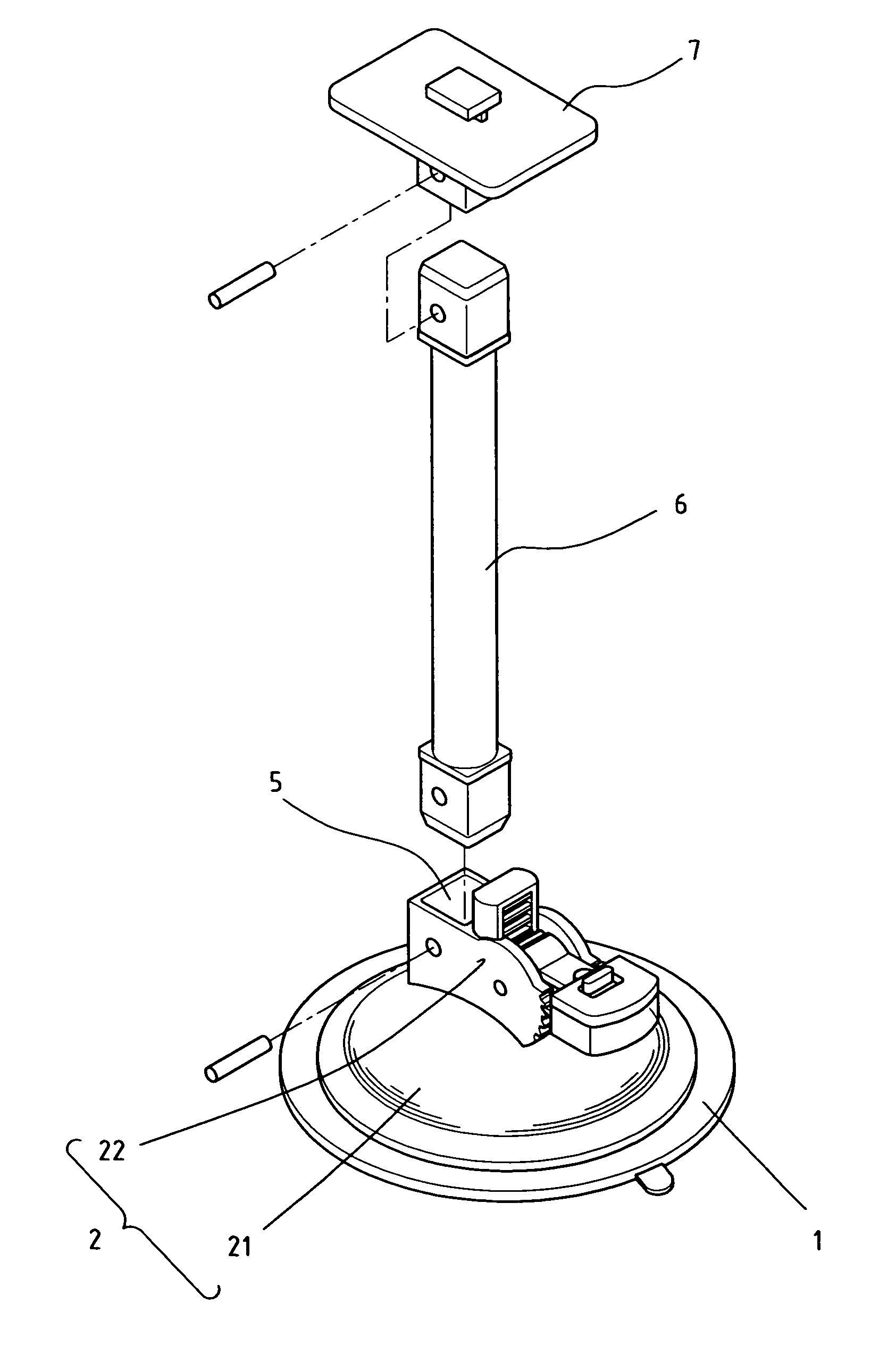
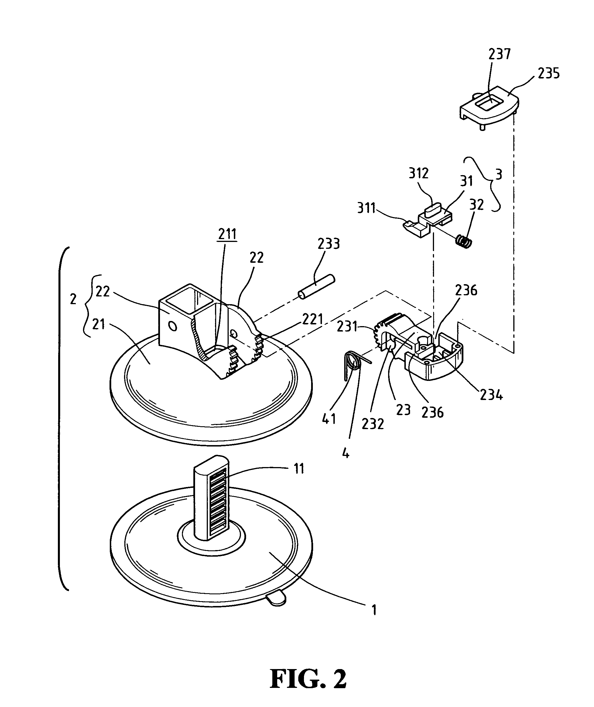
[0019]Referring to FIGS. 1 and 2, a vacuum suction apparatus in accordance with the present invention includes a suction cup 1, and a wheel base 2 that is installed over the suction cup 1. A rack 11 is vertically erected from the center of the suction cup 1 passing through the wheel base 2. The suction cup is formed by rubber or polyvinyl chloride (PVC) material, and the rack 11 is made out of material harder than the suction cup 1.

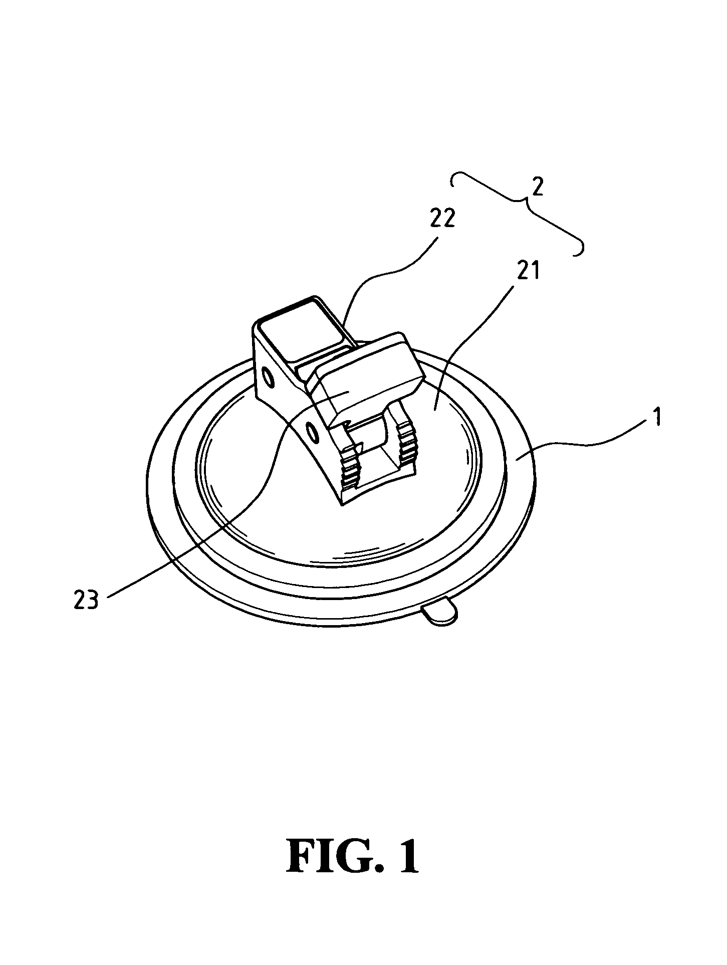
[0020]Referring to FIG. 3A, the wheel base 2 has a receptacle 21 attached by the suction cup 1 from underneath, a cogwheel 22 being fixed over the receptacle 21, and an adjustment lever 23 pivotally connected through a slot opening. The receptacle 21 is a circular body with a hunched back toward the center, with a slot opening 211 at the center that allows the rack 11 to pass through to the outside, also passing through the inner space of the cogwheel 22, where an adjustment lever 23 is pivotally connected having a pinion 231 on one end. Once assembled on...


PUM


Abstract

A vacuum suction apparatus with adjustment lever is disclosed. The structure of the vacuum suction apparatus includes a suction cup and a wheel base, which has a receptacle being attached by the suction cup from underneath, a semi-circular cogwheel being fixed on top of the receptacle, and an adjustment lever pivotally connected through an opening. The adjustment lever has a pinion on the bottom end, where the gearing of the pinion is to fit against corresponding gearing on the vertically erected rack at the center when the lever is in locked position. The upper portion of the lever also has a suction lock/release that allows the user to manually adjust the angle of the lever by pegging onto scooped cogwheel with a slider, so the suction strength can be adjusted desirably for continuously holding onto the same spot in extended use.

Description


Claims


Application Information

Patent Timeline
Owner FAN EAGLE
Why Eureka
Try Eureka