Connector

a technology of connecting rods and connectors, applied in the direction of coupling device connections, electrical discharge lamps, coupling device details, etc., can solve the problems of increased operating costs, failed insulation, defective connections, etc., and achieve the effect of avoiding defective connections and failed insulation, and preventing increase manufacturing and operating costs

Inactive Publication Date: 2006-04-04
DDK LTD
View PDF8 Cites 24 Cited by
  • Summary
  • Abstract
  • Description
  • Claims
  • Application Information

AI Technical Summary

Benefits of technology

[0007]It is an object of the invention to provide an improved connector capable of preventing its block from being deformed by heating in soldering or welding when connecting conductors, avoiding any defective connection and failed insulation, and preventing increase in manufacturing and operating cost to overcome all the disadvantages of the prior art.
[0010]In a preferred embodiment, the plate-shaped piece and the block are different in heat-resistance and are integrally formed with each other. Such an integral construction ensures easy and exact positioning of the contacts.
[0017](5) According to the invention the plate-shaped piece is made of a material having a melting point which is higher than 400° C. to eliminate deformations of the block and the plate-shaped piece and hence to prevent any defective or failed connection.

Problems solved by technology

The temperature at which thermal deformation of such a material may occur is 220° C. to 270° C. and its melting point is 220° C. to 300° C. In soldering or welding, however, the temperature instantaneously rises to about 300° C. to 1,000° C. and the temperature in use becomes approximately 300° C., so that such heated conditions would give rise to deformation of the block, defective connection, failed insulation and the like, which are serious problems to be solved.
The thermal deformation of the block leads to necessity to exchange the connector itself resulting in increased operating cost.

Method used


Image

  • Connector
  • Connector
  • Connector

Examples


Embodiment Construction

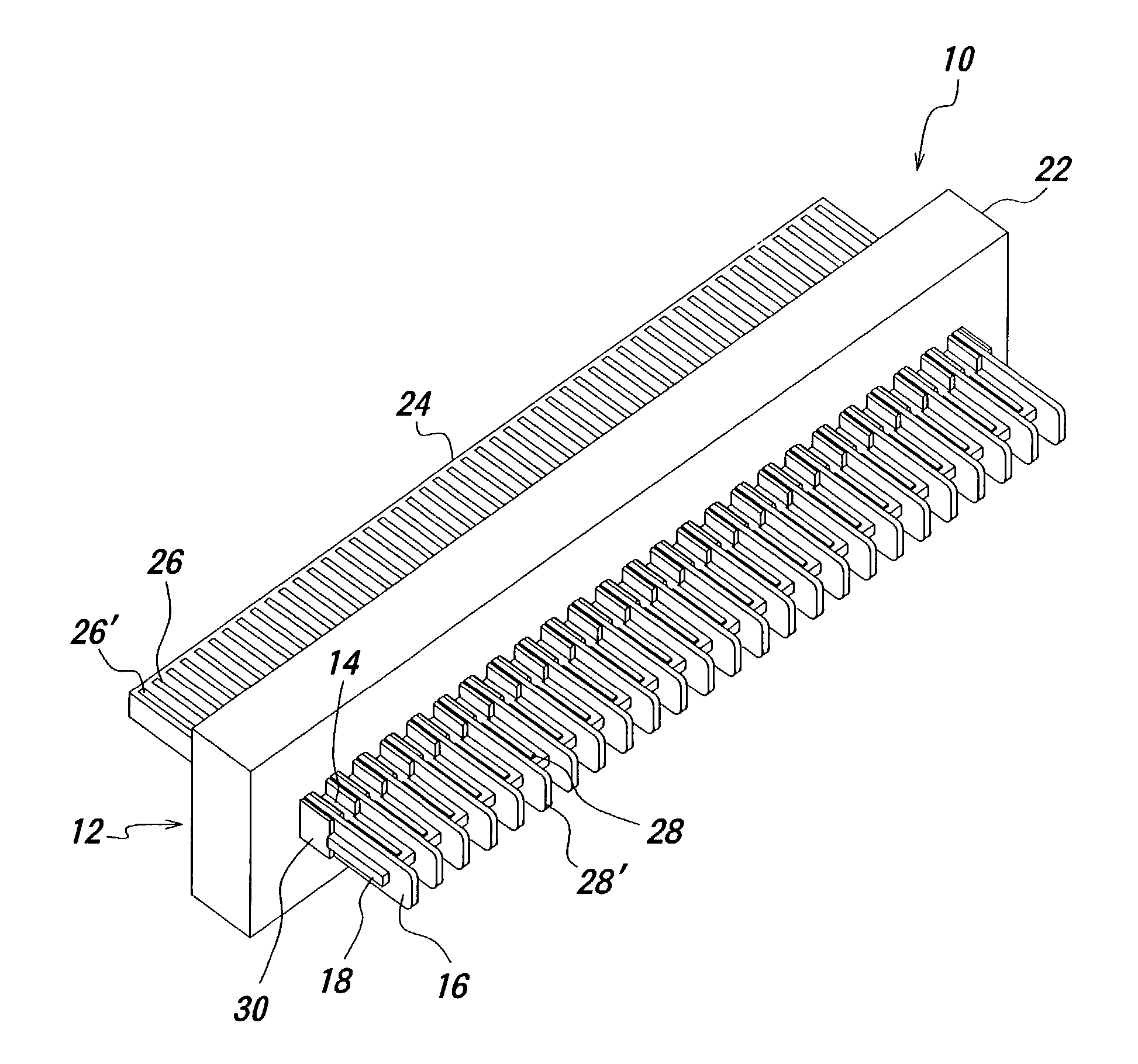
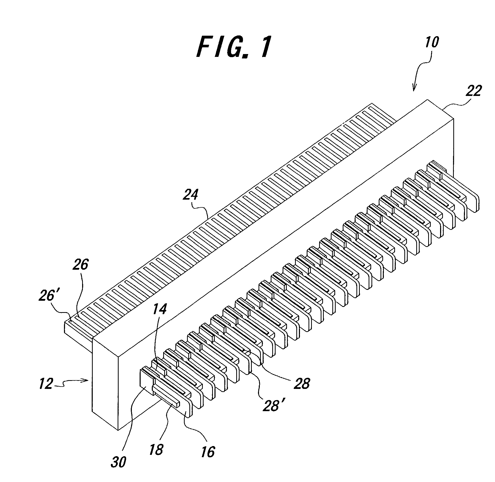
[0026]FIG. 1 illustrates in a perspective view a connector according to one preferred embodiment of the invention having a plate-shaped piece, one example of which is shown in a perspective view of FIG. 2A and another example of which formed with recesses is shown in a perspective view of FIG. 2B. FIG. 3 illustrates in a perspective view a connector using the plate-shaped piece shown in FIG. 2B according to another embodiment of the present invention. FIGS. 4A and 4B illustrate in perspective views a signal contact and a ground contact to be used in the connector according to the invention, respectively.

[0027]The connector 10 according to the first embodiment of the invention comprises a required number of signal contacts 14, a required number of ground contacts 16, a block 12 and a plate-shaped piece 18. These components will be explained in detail hereinafter.

[0028]Forming an important aspect of the connector of the present invention is the plate-shaped piece 18 which will be firs...


PUM


Abstract

A connector includes a block and a required number of contacts held and fixed in the block. A plate-shaped piece made of a heat resistant and electrically insulating material is fixed to the block on that side of the contacts to which conductors are connected. The plate-shaped piece is preferably formed with grooves with a predetermined interval on that surface of the piece on which the contacts are arranged. With this construction, it is possible to provide an improved connector which is able to prevent the block from being deformed due to heating in soldering and welding when connecting conductors, and is free from any defective connection and failed insulation without raising the manufacturing and operating cost.

Description

BACKGROUND OF THE INVENTION[0001]This invention relates to a connector for use in a personal computer or the like, and more particularly to a connector provided with a plate-shaped piece of a highly heat-resistant material arranged on that side to which conductors are connected.[0002]A hitherto used connector will be explained by referring to a perspective view of FIG. 5. The connector 40 of the prior art substantially consists of signal contacts 44, ground contacts 46 and a block 42. The signal contacts 44 and the ground contacts 46 are alternately arranged. Each of the signal contacts 44 consists of a contact portion 26 adapted to contact a mating contact, a fixed portion to be held and fixed to the block 42 and a connection portion 28 to be connected to a conductor. Similarly, each of the ground contacts 46 consists of a contact portion 26′, a fixed portion and a connection portion 28′ having the same functions as those in the signal contact 44.[0003]Connected to the connection p...

Claims


Application Information

Patent Timeline
Patent Type & Authority Patents(United States)
IPC IPC(8): H01R24/00H01R13/502H01R4/02H01R43/02
CPCH01R43/0263H01R4/027
Inventor OZAI, KAZUYUKI
Owner DDK LTD
Why Eureka
Try Eureka