Light device for automobile overhead lights

a technology for overhead lights and light devices, which is applied in the direction of lighting and heating equipment, instruments, lenses, etc., can solve the problems of large amount of energy being wasted, unpleasant—or even nuisance for the driver, and the second type of light described

Inactive Publication Date: 2006-04-11
VALEO VISION SA
View PDF16 Cites 9 Cited by
  • Summary
  • Abstract
  • Description
  • Claims
  • Application Information

AI Technical Summary

Benefits of technology

[0002]Its purpose is in particular to propose a particular embodiment of lights which, whilst comprising a shield intended to prevent diffusion of light upwards, obtains a sufficient light intensity for satisfactory viewing of certain elements placed in various areas situated above a central axis of the beam emitted by the light.

Problems solved by technology

However, a problem is posed with the second type of light described.
The regulatory requirements are then satisfied, but the light intensity diffused in the rectangle is such that it is unpleasant—or even a nuisance—for the driver.
However, such a method has several drawbacks: firstly the frosted surface diffuses light almost isotropically, a large quantity of energy being wasted, including in areas of the beam where the intensity is already relatively low; secondly, the production of molds for obtaining a frosted surface is very tricky, the mold itself being little by little polished by the glass used to manufacture the lens.

Method used


Image

  • Light device for automobile overhead lights
  • Light device for automobile overhead lights
  • Light device for automobile overhead lights

Examples


Embodiment Construction

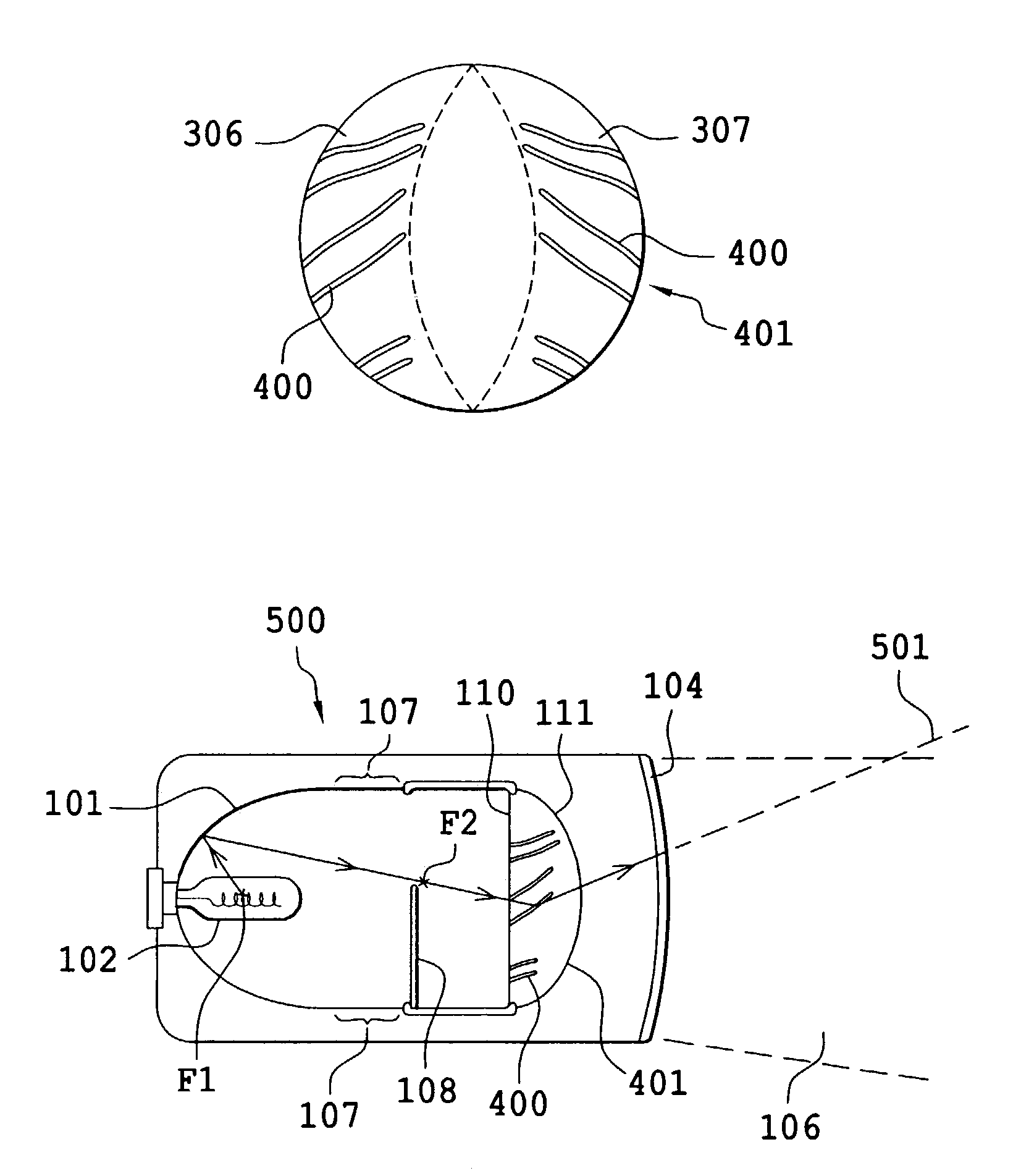
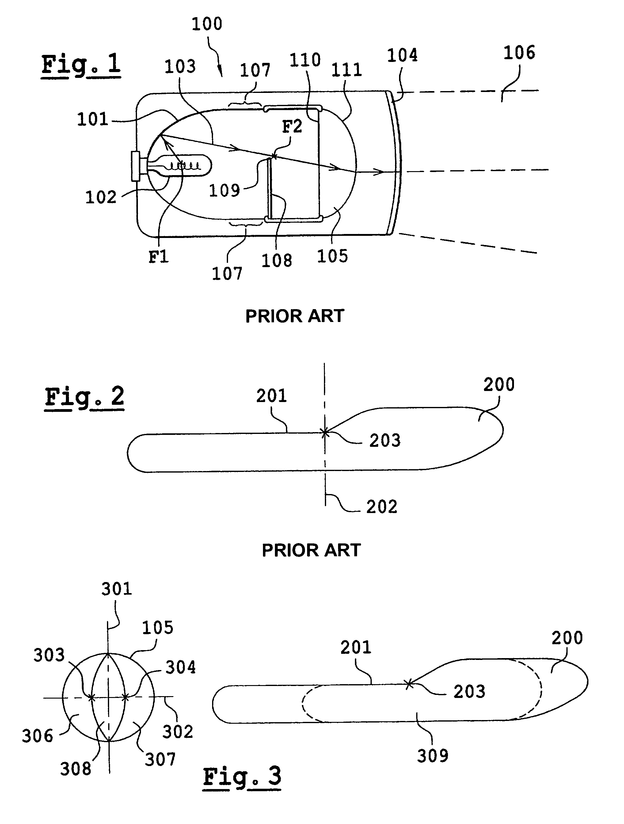
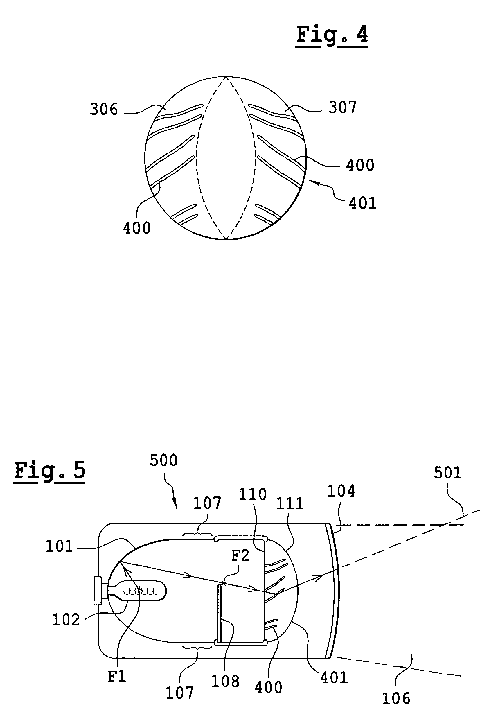
[0046]In the various figures, the elements which are common to several figures will have kept the same references. FIG. 3 shows a projection lens 105 in front view, that is to say as it can be seen when facing the light. The lens shown is circular; in other examples, it could be elliptical. A vertical axis 301 and a horizontal axis 302 intersect at the center of the circle 105. On a diameter supported by the horizontal axis 302, a first point 303 and a second point 304 are located, disposed so that they divide the diameter in question into three segments of substantially equal sizes. In this way three distinct areas are defined on the exit surface of the lens 105: a first side surface 306 included between the left-hand end of the lens and an arc of a circle passing through the point 303 and the ends of the diameter supported by the vertical axis 301; a second side surface 307 included between the right-hand end of the lens and an arc of a circle passing through the point 304 and the...


PUM


Abstract

The present invention relates to a projection device in which a projection lens has undergone arrangements at its exit surface, and more particularly side areas of this exit surface. The arrangements are intended to divert certain light rays emitted by a light source of the light in order to illuminate overhead lights without interfering with the homogeneity of the light beam of said light. The arrangements made may consist of protuberances in the form of serrations.

Description

FIELD OF THE INVENTION[0001]The object of the present invention is a light device equipping motor vehicles and obtaining overhead lights points in accordance with the regulations.BACKGROUND OF THE INVENTION[0002]Its purpose is in particular to propose a particular embodiment of lights which, whilst comprising a shield intended to prevent diffusion of light upwards, obtains a sufficient light intensity for satisfactory viewing of certain elements placed in various areas situated above a central axis of the beam emitted by the light.[0003]The field of the invention is, in general terms, that of automobile lights. In this field, various types of light are known, amongst which there are essentially:[0004]side lights, of low intensity and range;[0005]dipped lights, of higher intensity and with a range on the road of approximately 70 meters, which are used essentially at night and where the distribution of the light beam is such that it does not dazzle the driver of a vehicle being passed...

Claims


Application Information

Patent Timeline
Patent Type & Authority Patents(United States)
IPC IPC(8): B60Q1/00F21V5/00G02B3/00
CPCF21S48/1258G02B3/00F21S48/1283F21S41/255F21S41/275
Inventor ALBOU, PIERRE
Owner VALEO VISION SA
Why Eureka
Try Eureka