System and method of identifying an object in a laser beam illuminated scene based on material types

a laser beam and illumination scene technology, applied in the direction of counting objects on conveyors, using reradiation, instruments, etc., can solve the problem that most sophisticated passive ir sensors and active radar cannot automatically classify a wide range of targets or such a diverse area, and the information is not necessarily available on the type of thermal gradient detected

Inactive Publication Date: 2006-04-11
ROSEMOUNT AEROSPACE
View PDF5 Cites 55 Cited by
  • Summary
  • Abstract
  • Description
  • Claims
  • Application Information

AI Technical Summary

Problems solved by technology

No information is necessarily available on the type of thermal gradient detected.
Even the most sophisticated passive IR sensors and active radar cannot automatically classify a wide range of targets or such a diverse area as described herein.
Current unattended sensors have notoriously high false alarm rates due to the inability to capture enough information necessary to make an intelligent decision.
With today's technology, sensing systems might falsely identify a dog as a threat, wasting valuable time and attention.
Further, since these passive systems rely on reflected sunlight, the presence of clouds and infrared thermal emissivity can affect and alter the passively collected energy.
As with the basic technology, the hyperspectral sensing approach also requires extensive calibration and is often not well suited for battlefield environments.
However, LPAS can not establish objects that are different than those expected in the naturally occurring or urban environment.
While LOAS, LPAS, and other laser or conventional radar systems provide object detection, they do not provide the real intelligence in order to classify the type of threat which is desirable to aid military forces operating in the wide range of environments.

Method used


Image

  • System and method of identifying an object in a laser beam illuminated scene based on material types
  • System and method of identifying an object in a laser beam illuminated scene based on material types
  • System and method of identifying an object in a laser beam illuminated scene based on material types

Examples


Embodiment Construction

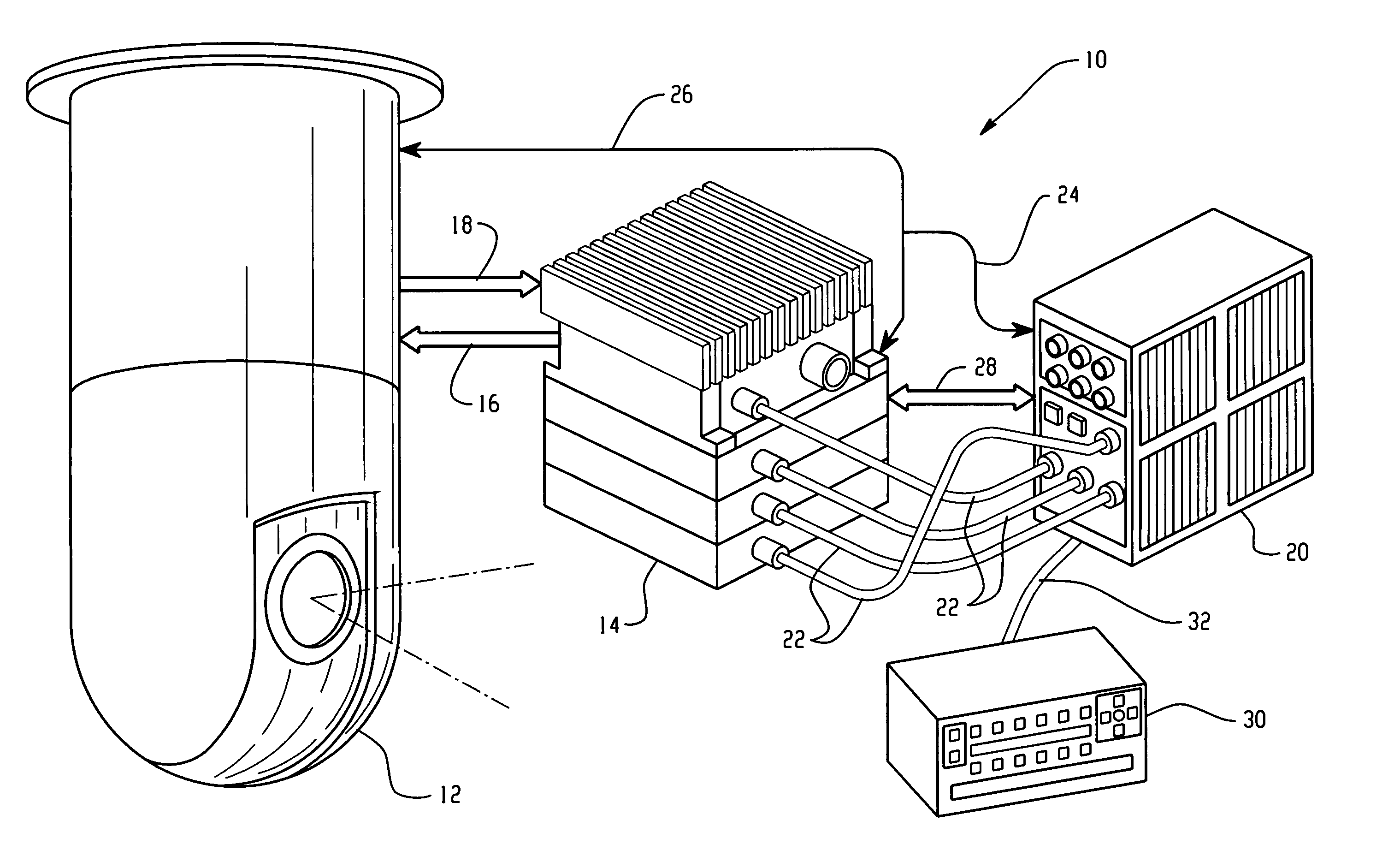
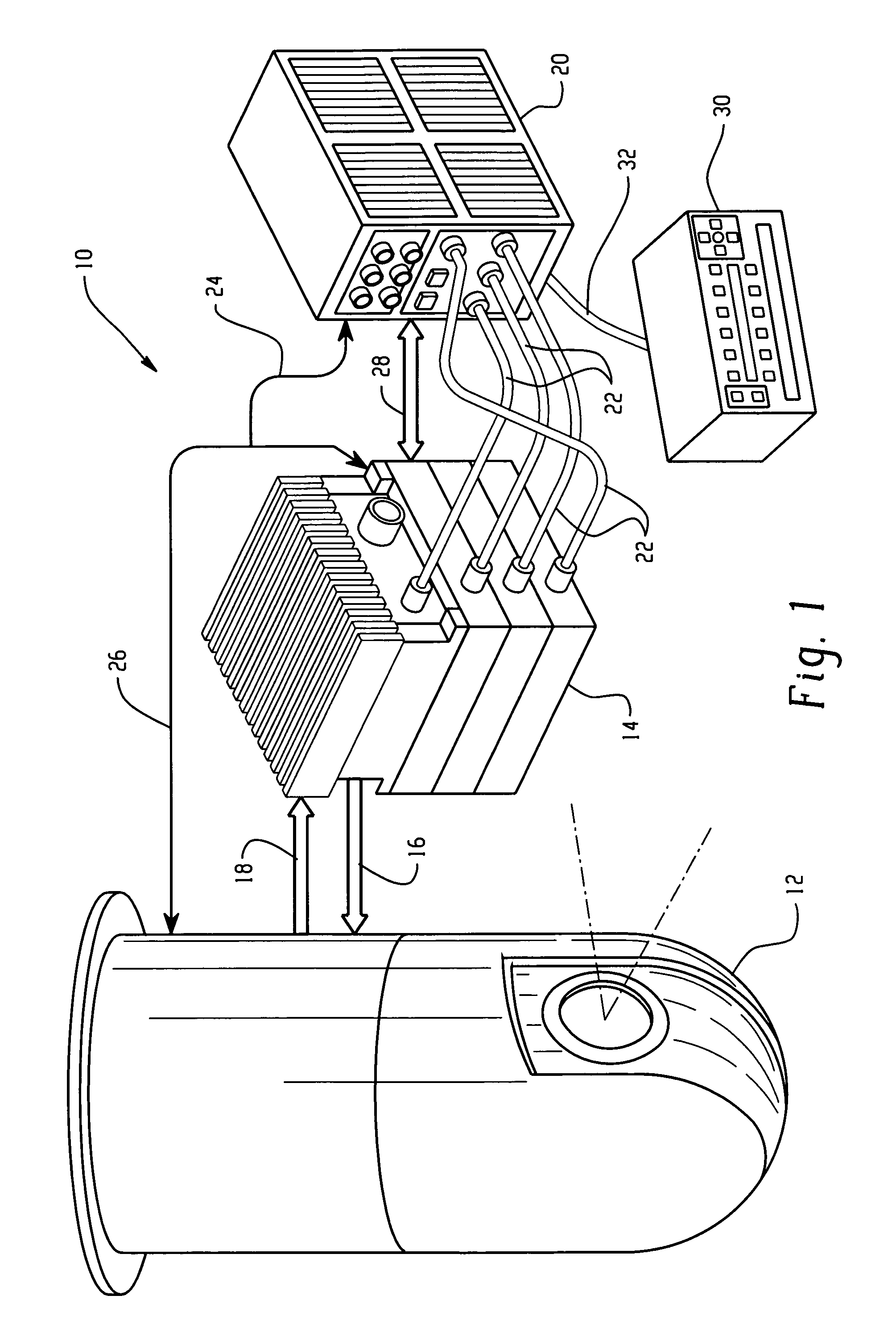
[0024]One aspect of the present invention involves the seamless data fusion of range-resolved laser data imagery with multi-spectral near-infrared (IR) reflectance data. Unlike passive remote sensors, the multi-spectral reflectance data image is formed through active laser illumination of a target area simultaneously at a plurality of discrete wavelengths or wavelength bands. By exploiting the near-infrared absorption and reflectance characteristics of different materials using an active laser source, dependencies on sunlight are eliminated. The laser system of the present invention will be of sufficient spatial and spectral resolution to resolve the fine material details such as the metal barrel of a rifle against the clothing fabric of a non-combatant hundreds of meters down range. This may be accomplished for stationary and moving scenarios.

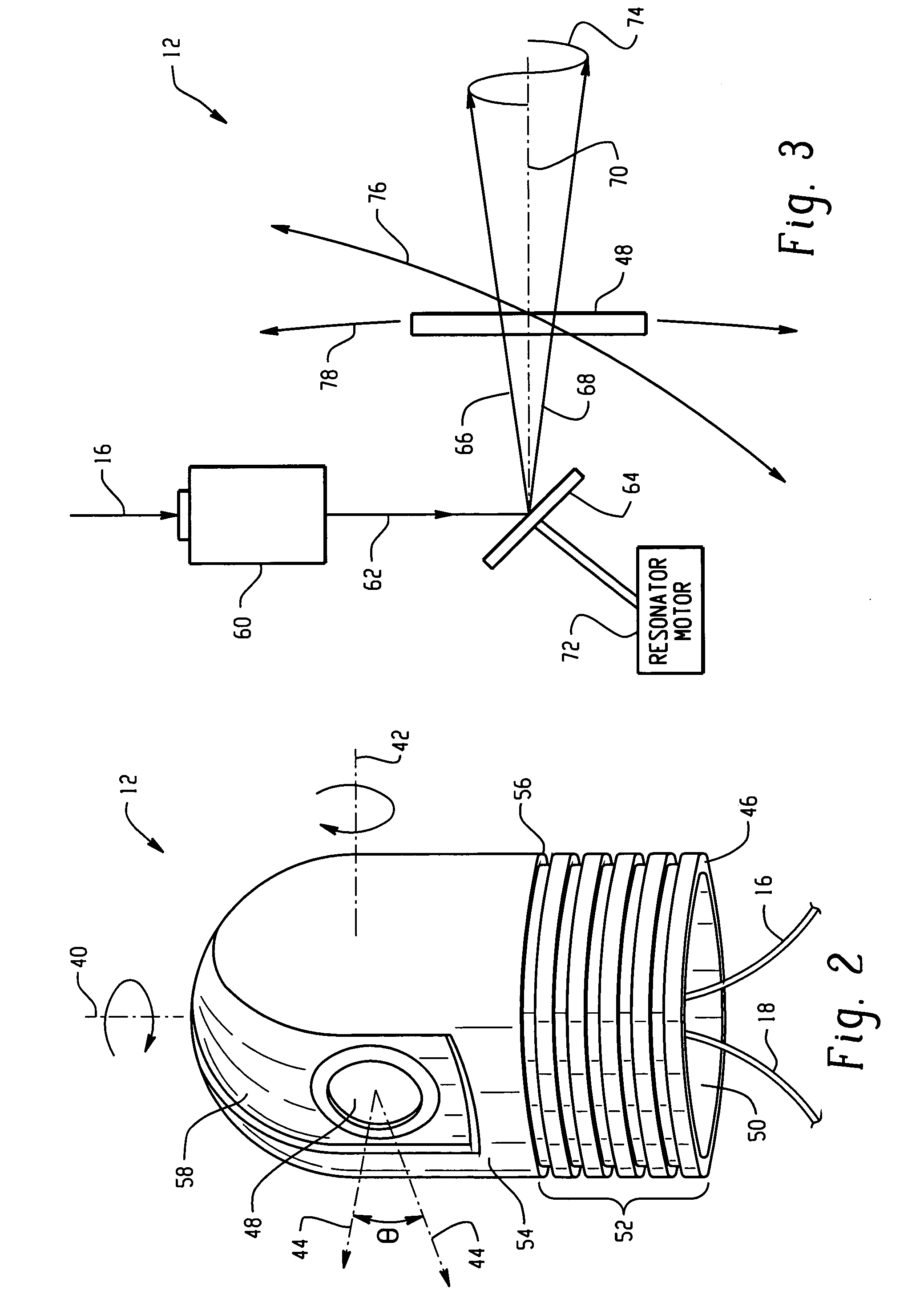
[0025]In the present system, a single, compact scanning laser system will simultaneously emit pulses of laser light at a plurality of wavelen...


PUM

PropertyMeasurementUnit
wavelengthaaaaaaaaaa
angleaaaaaaaaaa
wavelengthsaaaaaaaaaa

Abstract

A method of identifying an object in a laser beam illuminated scene based on material types comprises the steps of: emitting a pulsed beam of laser energy, each beam pulse comprising a plurality of different discrete wavelength emission components; illuminating a predetermined scene with the pulsed beam; receiving return laser pulses from objects within the illuminated scene, each return laser pulse comprising return components corresponding to the plurality of different discrete wavelength emission components; determining spectral reflectance values for the plurality of return components of each return laser pulse; determining a material type for each return laser pulse of the illuminated scene based on the plurality of reflectance values of the corresponding return pulse; indexing each determined material type to a position in the illuminated scene; and identifying an object in the illuminated scene based on material types and indexed positions thereof in the scene. A counterpart system for carrying out the method is also disclosed.

Description

BACKGROUND OF THE INVENTION[0001]The present invention is related generally to the detection of threats to a target using active laser technologies, and more particularly, to an active laser system and method of identifying and classifying an object in a laser beam illuminated scene based on material types.[0002]Mobile military forces can operate in a wide range of environments. These environments can be varied in material types such as naturally occurring sand and vegetation to snow; urban areas with vehicles and buildings; or mountainous terrain. In all cases, man-made or naturally occurring materials radiate reflected and emitted energy based on internal and external sources. Hot objects, for example, radiate heat, a process that can be exploited by passive thermal imagers to discriminate against a cooler background. However, this detection is merely an indication of a thermal gradient. No information is necessarily available on the type of thermal gradient detected.[0003]Primary...

Claims


Application Information

Patent Timeline
Patent Type & Authority Patents(United States)
IPC IPC(8): H01J40/14G01N21/25G01N21/35G01S7/48G01S7/484G01S17/87G01S17/89G06V10/56
CPCG01N21/251G01N21/359G01S7/4802G06K9/4652G01S17/87G01S17/89G01S7/484G06V10/56
Inventor JAMIESON, JAMES R.RAY, MARK D.MENEELY, CLINTON T.
Owner ROSEMOUNT AEROSPACE
Why Eureka
Try Eureka