

Very narrow band, two chamber, high rep-rate gas discharge laser system
a laser system and gas discharge technology, applied in the field of gas discharge laser systems of oscillator amplifiers, can solve the problems of adversely affecting wavelength and/or bandwidth, and affecting the quality of the beam quality specification of pulse energy stability, wavelength stability and bandwidth have become increasingly tight, and the output power is good, the effect of improving the control of wavelength and bandwidth
- Summary
- Abstract
- Description
- Claims
- Application Information
AI Technical Summary
Benefits of technology
Problems solved by technology
Method used
Image

Examples
first preferred embodiment
Three Wavelength Platform
First General Layout
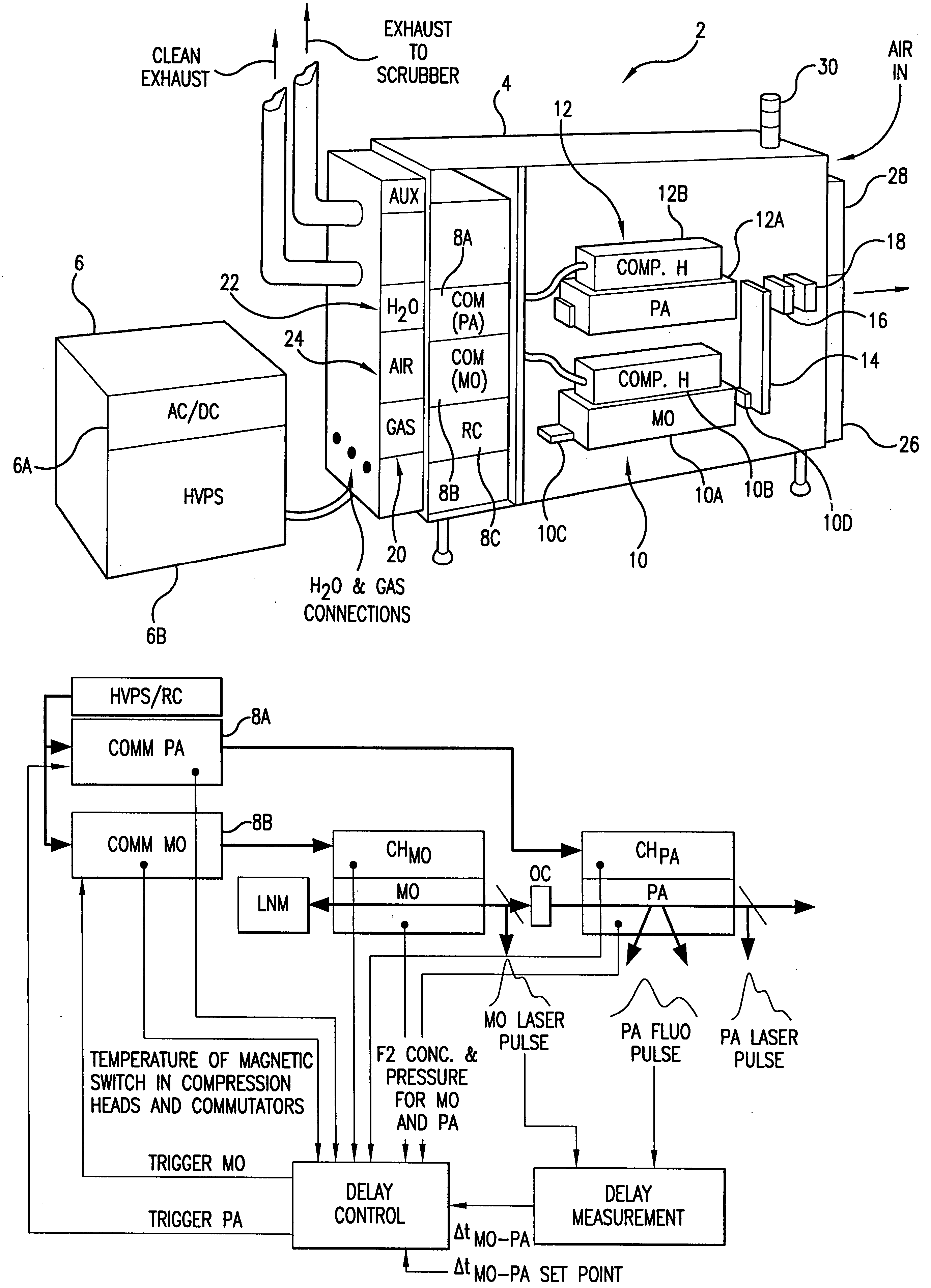
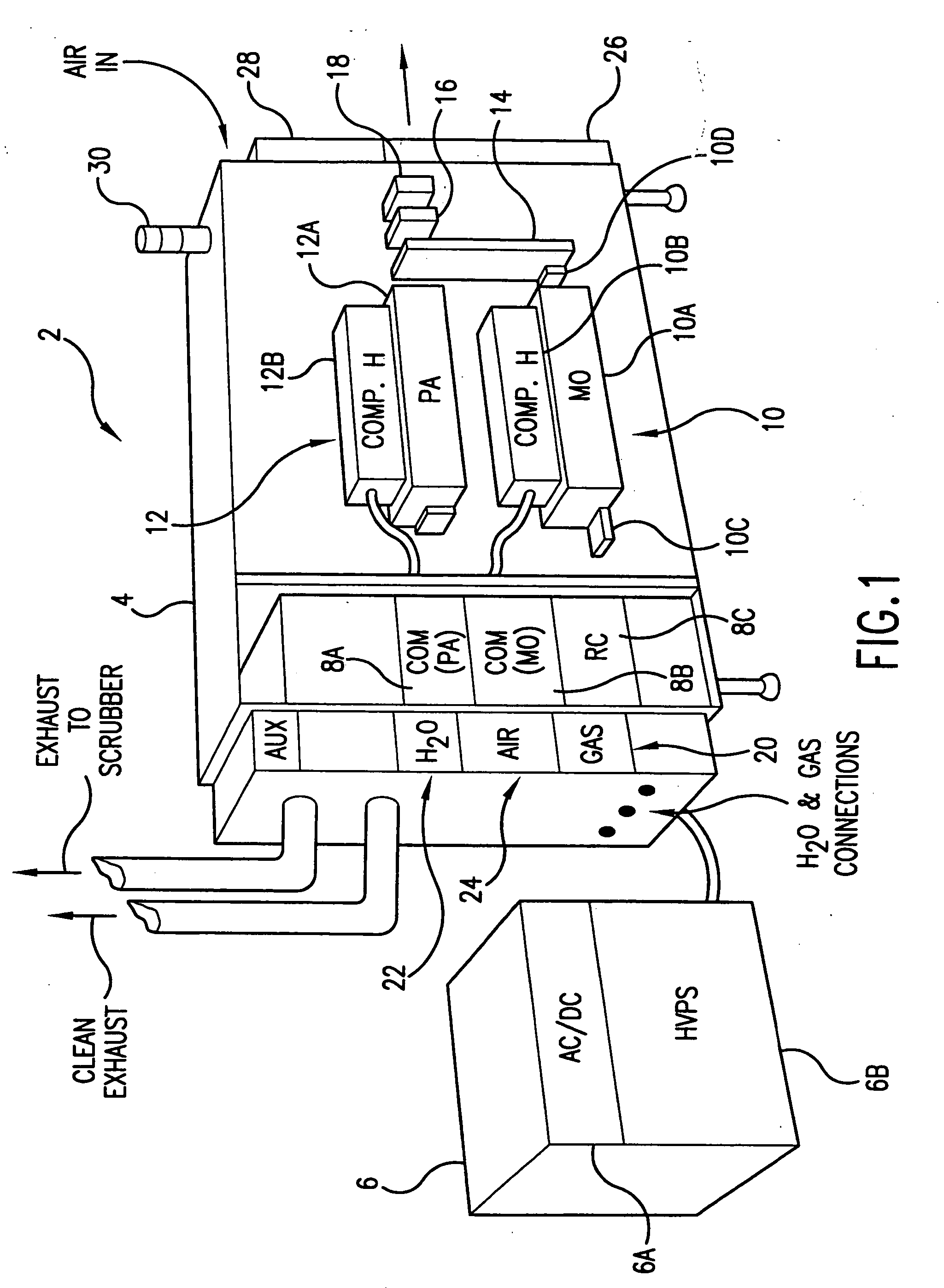
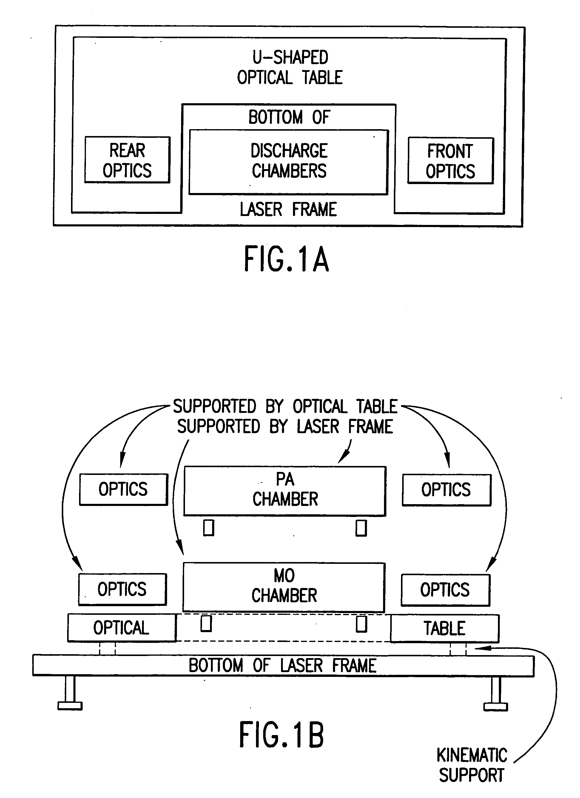
[0046]FIG. 1 is a perspective view of a first preferred embodiment of the present invention. This embodiment is an injection seeded narrow band excimer laser system configured as a MOPA laser system. It is specially designed for use as a light source for integrated circuit lithography. The major improvement in the present invention as exemplified in this embodiment over the prior art lithography lasers is the utilization of injection seeding and in particular a master oscillator-power amplifier (MOPA) configuration with two separate discharge chambers.
[0047] This first preferred embodiment is an argon-fluoride (ArF) excimer laser system; however, the system utilizes a modular platform configuration which is designed to accommodate either krypton-fluoride (KrF), ArF or fluorine (F2) laser components. This platform design permits use of the same basic cabinet and many of the laser system modules and components for either of these three t...
PUM
 Abstract
Description
Claims
Application Information