Monitored laser shock peening

Inactive Publication Date: 2005-05-05
GENERAL ELECTRIC CO
View PDF28 Cites 32 Cited by
  • Summary
  • Abstract
  • Description
  • Claims
  • Application Information

AI Technical Summary

Problems solved by technology

Since each laser pulse produces a small explosion at the peening site, the water film is temporarily disrupted.
If the repetition rate is excessive and the water film is not re-established promptly, the succeeding laser pulse will not be suitably confined, thus degrading the peening process and red

Method used


Image

  • Monitored laser shock peening
  • Monitored laser shock peening
  • Monitored laser shock peening

Examples


Embodiment Construction

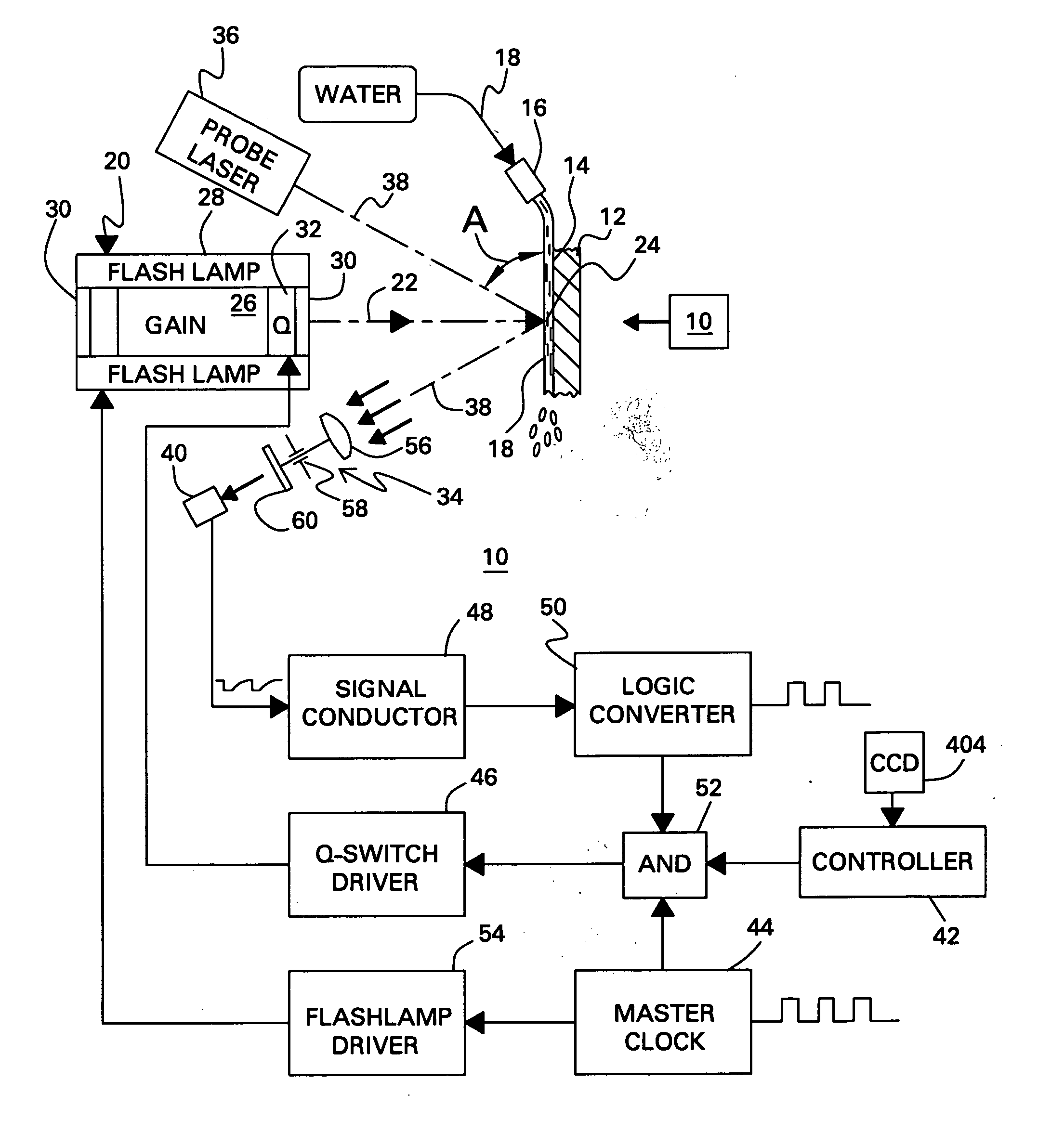
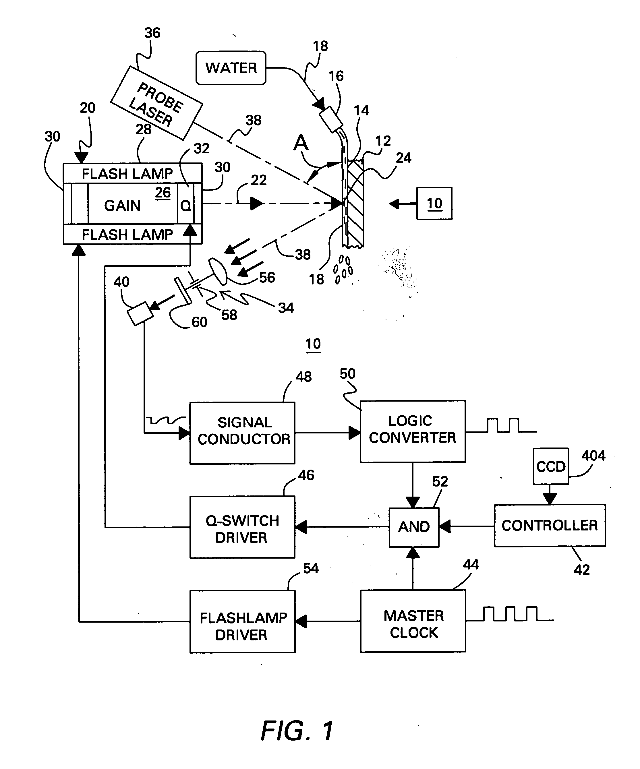
[0014] In FIG. 1, a laser shock peening (LSP) system 10 in accordance with an exemplary embodiment of the invention is shown configured for laser shock peening one side of a metal workpiece 12 in order to introduce plastic deformation and resulting compressive residual stress.

[0015] An identical system 10 is illustrated schematically in the box to the right of workpiece 12 in FIG. 1 for simultaneously peening the opposite side of the workpiece in a preferred embodiment which balances the compressive stresses introduced into the workpiece. Accordingly, the system may be used over any surface of a metal workpiece either alone or in conjunction with peening of opposite surfaces thereof as desired.

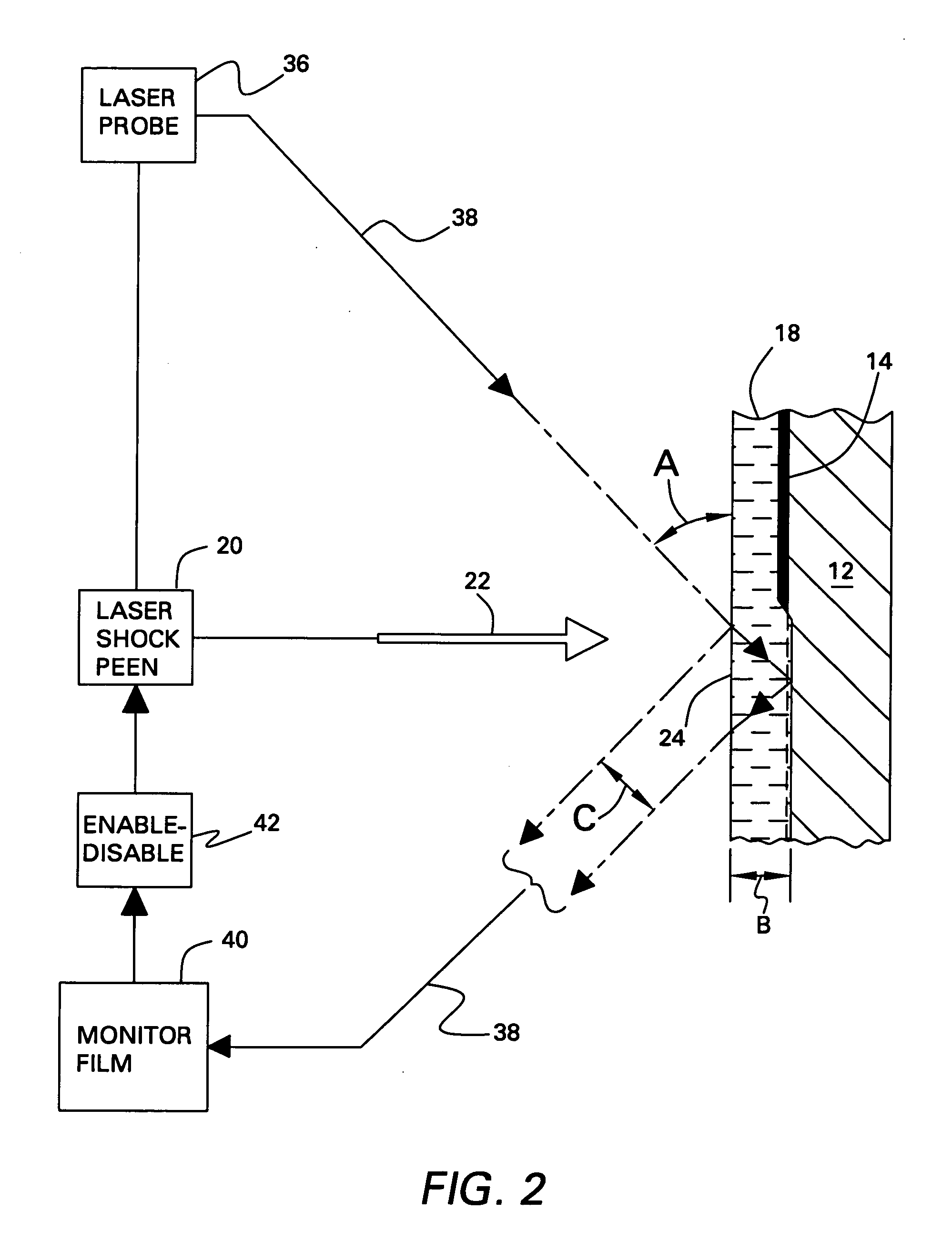
[0016] Workpiece 12, illustrated in enlarged part in FIG. 2, may have any conventional configuration for which laser shock peening of the outer surface of the workpiece is desired. LSP is effected by initially providing a light-absorbing or ablative layer 14 over the exposed surface of the w...


PUM

PropertyMeasurementUnit
Angular velocityaaaaaaaaaa
Thicknessaaaaaaaaaa
Electric potential / voltageaaaaaaaaaa

Abstract

A pulse laser is configured for projecting a pulsed laser beam at a target site on a fluid film atop a workpiece for laser shock peening the workpiece. The fluid film is monitored by a probe laser which projects a probe laser beam at the target site, and an optical detector which detects reflection of the probe beam from the target site. The pulse laser is coordinated by the detector in order to emit the pulsed beam in response to the condition of the monitored film.

Description

BACKGROUND OF THE INVENTION [0001] This invention relates to surface peening of metal workpieces, and, more specifically, to laser shock peening thereof. [0002] Fatigue strength of metal parts may be improved by introducing compressive residual stresses in the surface of such parts. This is typically accomplished by shot peening the surface with small metal shot to plastically deform and compress the metal surface layer. The metal surface must be uniformly peened to ensure the efficacy of the peening process. [0003] Laser shock peening (LSP) is a modern development in peening, and uses a high peak-power laser to generate mechanical shock waves in order to produce compressive residual stresses in the metal surface. This process is performed by applying an absorbing material over the metal surface, such as black paint or tape, to absorb energy from the laser beam and produce a rapidly expanding or exploding plasma. The plasma produces a shock wave capable of plastically deforming the ...

Claims


Application Information

Patent Timeline
IPC IPC(8): G01B11/06B23K26/00B23K26/03B23K26/18C21D10/00C23C26/00
CPCB23K26/03B23K26/032B23K26/009C21D10/005B23K26/18
Inventor WARREN, RICHARD EDWIN JR.STAVER, PHILLIP RANDALL
Owner GENERAL ELECTRIC CO
Why Eureka
Try Eureka