Full-fiber optical path full-waveform laser radar system

A technology of laser radar and full waveform, which is applied in the direction of radio wave measurement system, electromagnetic wave re-radiation, utilization of re-radiation, etc., can solve the problem that the laser pulse waveform cannot be obtained, and achieve the effect of reducing complexity

Active Publication Date: 2014-07-02
BEIHANG UNIV
View PDF5 Cites 33 Cited by
  • Summary
  • Abstract
  • Description
  • Claims
  • Application Information

AI Technical Summary

Problems solved by technology

[0003] In the invention patent applied by Li Xiaolu (application number: 201310093384.1), in the full waveform laser radar system, the laser beam adopts the way of spatial transmission, and the waveform of the emitted laser pulse needs to be calibrated before the system measurement. For a single measurement, Only the laser pulse echo waveform can be obtained, but the emi

Method used


Image

  • Full-fiber optical path full-waveform laser radar system
  • Full-fiber optical path full-waveform laser radar system
  • Full-fiber optical path full-waveform laser radar system

Examples


Embodiment Construction

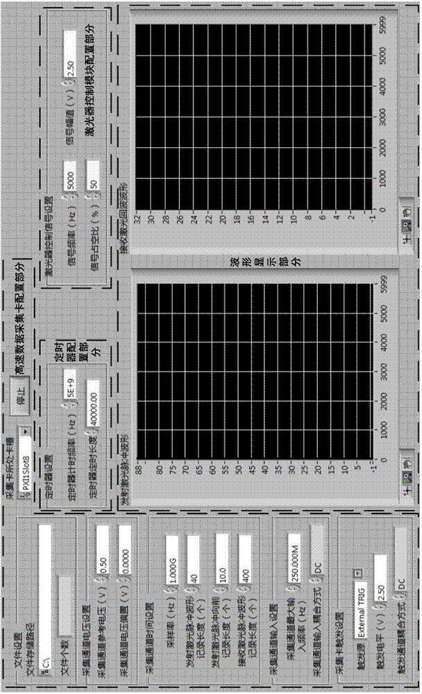
[0018] Before the system works, set the working parameters of the system with the help of the software unit. The software unit mainly completes the parameter configuration before the full-fiber optical path full-waveform laser radar system starts to work, as well as the real-time display of the transmitted laser pulse waveform and the received laser pulse waveform. The software interface is as follows: figure 2 as shown,

[0019] The software unit is developed based on the Labview platform. The front panel interface consists of a high-speed data acquisition card configuration part, a timer configuration part, a laser control module configuration part and a waveform display part. The high-speed acquisition card configuration part includes file settings, acquisition channel voltage settings, acquisition channel time settings, acquisition channel input settings and acquisition card trigger settings. File settings include file storage path settings and the display of the number o...


PUM


Abstract

The invention discloses a full-fiber optical path full-waveform laser radar system. The laser radar system comprises a control unit, a laser source, a laser beam splitting unit, a laser emitting unit, a data reading reference position generating unit, a laser detecting unit, a data acquiring unit and a software unit. The control unit controls a pulse laser to emit laser pulses, and the laser pulses are divided into an emitted laser pulse beam, an emitted laser pulse waveform acquisition beam and an emitted laser pulse marking beam through the laser beam splitting unit; after being subjected to target scattering, the emitted laser pulse beam enters the data acquiring unit through the laser detecting unit to serve as the received laser pulse waveform to be acquired, and a human-computer interaction interface is provided by the software unit. The laser radar system breaks through the limitation that a convectional laser radar can only measure a limited amount of distance and intensity data, complete fiberization of a full-waveform laser radar optical path is achieved through fiber components, and the debugging flexibility and the system integration simplification of a full-waveform laser radar are effectively enhanced.

Description

technical field [0001] The invention relates to the field of laser radar measurement, in particular to an all-fiber optical path full-waveform laser radar system. Background technique [0002] Lidar is an active remote sensing technology with the help of laser. It mainly measures the time for laser pulses to travel between the target and the LiDAR platform, and obtains the distance between the LiDAR platform and the target according to the relationship between the distance and the speed of light and time. The action of the scanning device, the laser radar can complete the scanning of the target surface, and combine the position and attitude data of the laser radar platform to obtain the digital surface model and digital elevation model of the target. Due to the fact that the pulse laser used in practice has a certain divergence angle, the emitted laser pulse beam propagates forward in the form of an approximate cone. When the laser pulse beam interacts with the target, it is...

Claims


Application Information

Patent Timeline
IPC IPC(8): G01S17/02
CPCG01S7/486G01S17/02
Inventor 徐立军李端李小路孔德明马莲
Owner BEIHANG UNIV
Why Eureka
Try Eureka