
Method, control circuit, computer program product and printing device for an electrophotographic process with temperature-compensated discharge depth regulation

a control circuit and electrophotography technology, applied in printing, printing, electromagnetography, etc., can solve the problems of insufficient fast process speed, insensitive photoconductor drum, and quality of printed documents falling below a certain minimum quality criterion, and achieve good inking

Active Publication Date: 2006-04-11
OCE PRINTING SYST
View PDF14 Cites 129 Cited by
  • Summary
  • Abstract
  • Description
  • Claims
  • Application Information

AI Technical Summary

Benefits of technology

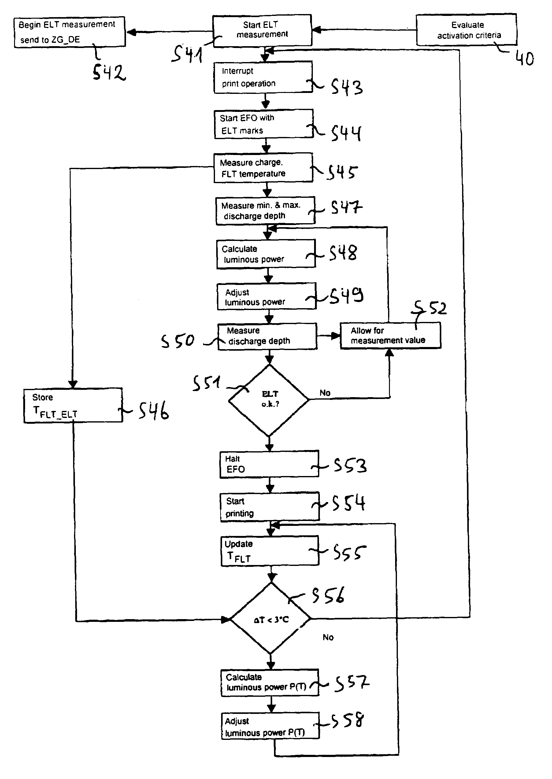
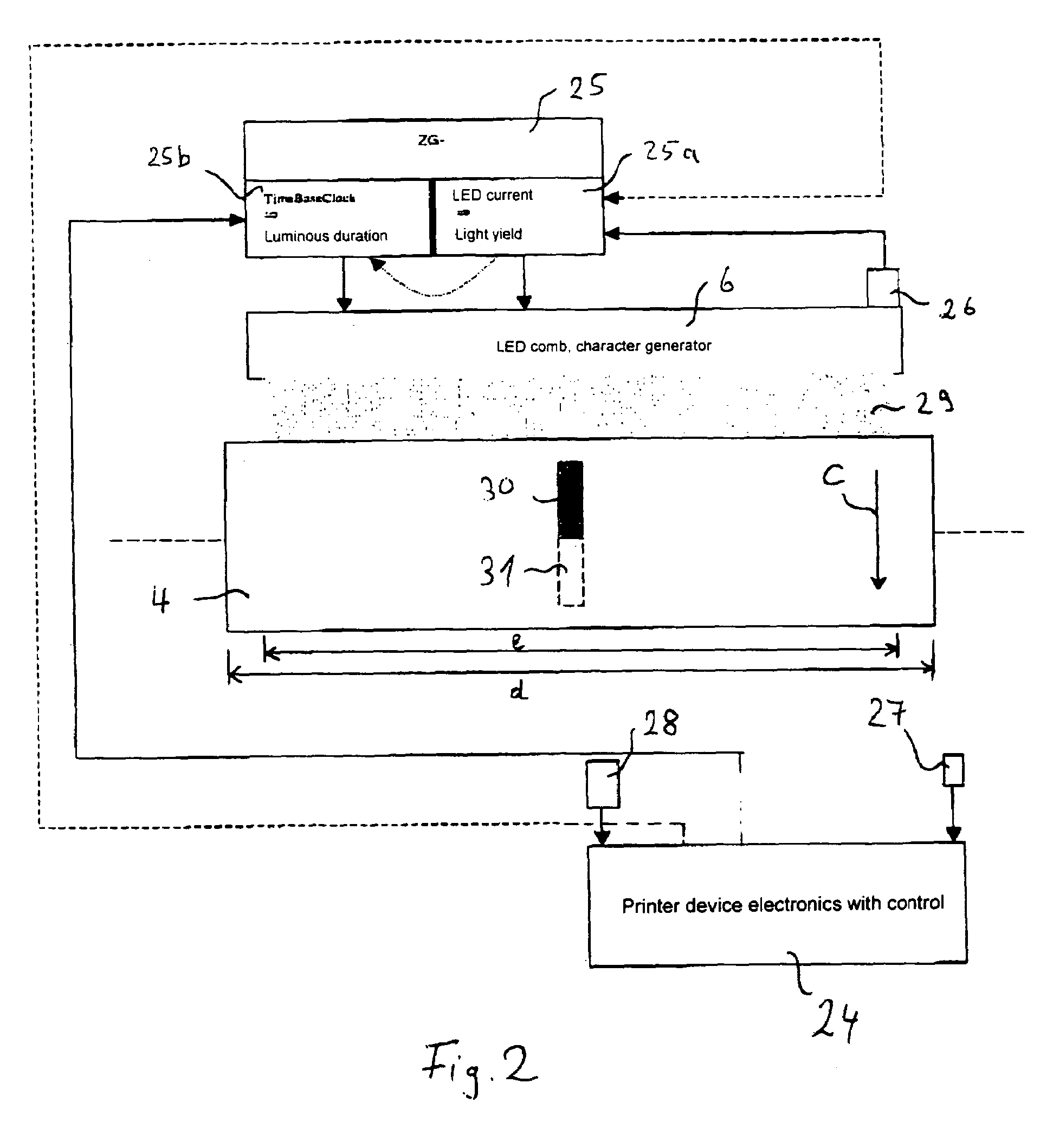
"The invention aims to stabilize the development process on a latent charge image, regardless of different operating conditions, to achieve a good inking quality. It also addresses the issue of insensitive photoconductor drums and fast process speed in cold printers, to ensure a high printing quality on the first printed page. The control device and method of the invention use a temperature-sensitive photoconductor layer that becomes more sensitive with rising temperature, allowing for a deeper discharge and lower luminous power with rising temperature. Temperature compensation is provided for the light source and photoconductor layer through at least one of current flowing through the light source and exposure time of the light source. The temperature compensation is based on a measurement event where the discharge depth of the photoconductor layer occurs given predetermined luminous duration and predetermined current through the light source, with the temperature of the light source measured during the measurement event being used as a reference value for the temperature compensation of the light source."

Problems solved by technology

Especially in cold printers that have not yet achieved the operating temperature, an insensitive photoconductor drum and a fast process speed are not sufficient for the initial luminous power of a character generator to achieve the necessary discharge depth for regions of the printing image to be exposed.
Depending on conditions and height of the variation, this can lead to the quality of the printed documents falling below a certain minimum quality criterion.

Method used


Image

  • Method, control circuit, computer program product and printing device for an electrophotographic process with temperature-compensated discharge depth regulation
  • Method, control circuit, computer program product and printing device for an electrophotographic process with temperature-compensated discharge depth regulation
  • Method, control circuit, computer program product and printing device for an electrophotographic process with temperature-compensated discharge depth regulation

Examples


Embodiment Construction

[0015]For the purposes of promoting an understanding of the principles of the invention, reference will now be made to the preferred embodiments illustrated in the drawings and specific language will be used to describe the same. It will nevertheless be understood that no limitation of the scope of the invention is thereby intended, such alterations and further modifications in the illustrated device, and / or method, and such further applications of the principles of the invention as illustrated therein being contemplated as would normally occur now or in the future to one skilled in the art to which the invention relates.

[0016]According to a first aspect, to optimize the charge image generation in an electrophotographic process, whereby a light-sensitive and temperature-sensitive photoconductor layer is exposed pixel-by-pixel with a temperature-sensitive light source, the photoconductor layer becomes more sensitive with rising temperature. Thus it discharges deeper given predetermin...


PUM


Abstract

With a control device to optimize charge image generation in an electrophotographic process, a light-sensitive and temperature-sensitive photoconductor layer is exposed pixel-by-pixel with a temperature-sensitive light source. The photoconductor layer becomes more sensitive with rising temperature, such that given a predetermined light quantity it discharges deeper. With rising temperature, given the same actuating power, the light source emits a lesser luminous power. The luminous power of the light source and the discharge depth of the photoconductor layer are temperature-dependent via adjustment of the current and / or the luminous duration that flows through the light source and / or the luminous duration. During the measurement of the discharge depth, a temperature measured in the course of the measurement event is used as a reference value for the temperature compensation of the light source.

Description

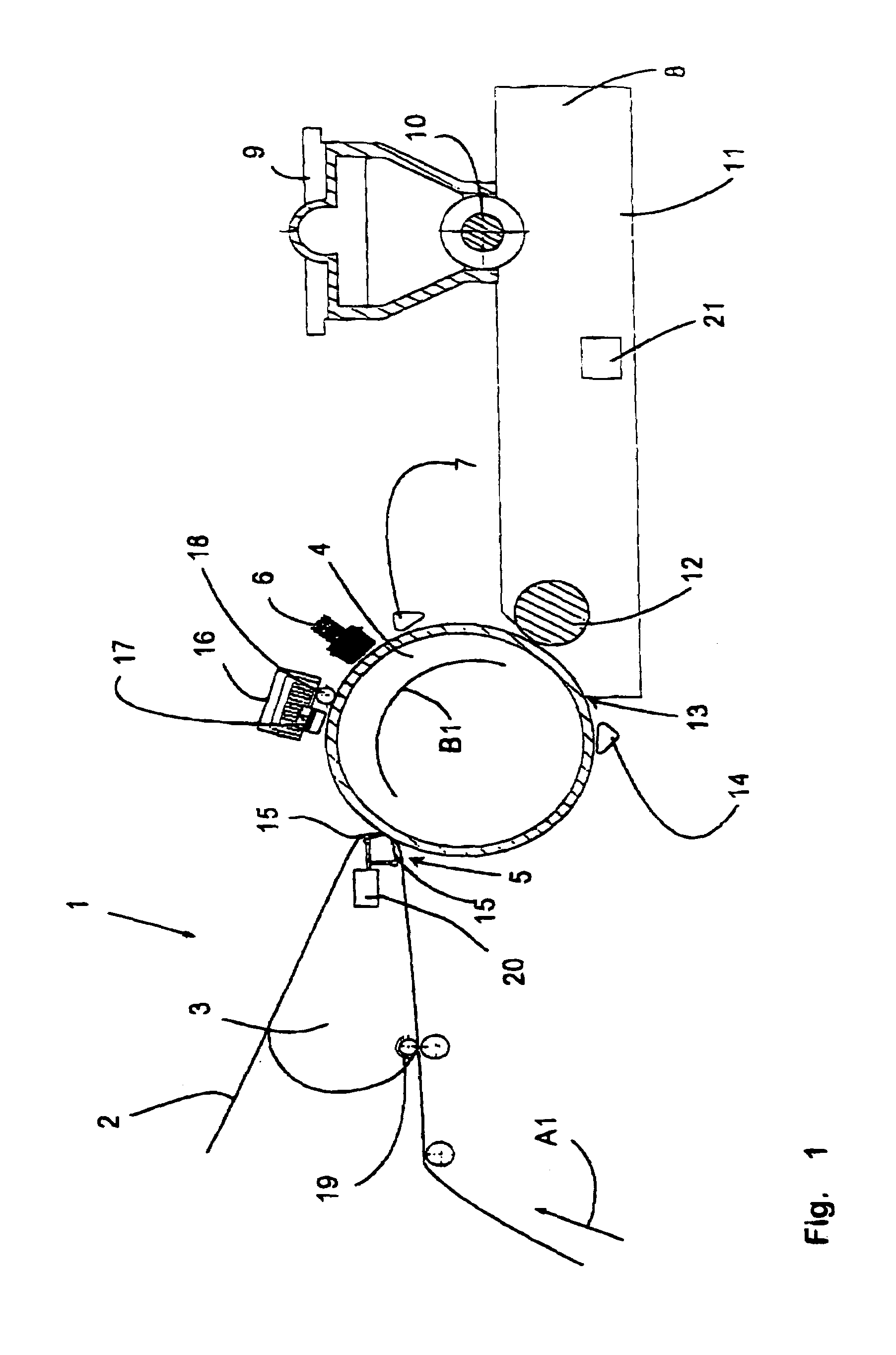
BACKGROUND OF THE INVENTION[0001]The invention concerns printing devices. It concerns in particular a method, a control circuit, a computer program product and a printing device for an electrophotographic process with temperature-compensated discharge depth regulation.[0002]An electrophotographic printing device is, for example, known from WO 00 / 41038. Information is thereby transmitted via a plurality of light sources (LED comb) or a luminosity-modulated laser beam onto a photoelectric layer (photoconductor), and therewith generates a charge image on the photoconductor. The latent charge image then passes through a developer station in which regions of different charge of the photoconductor are inked differently with toner. To stabilize such a developer process in spite of different operating conditions of the printing system, in particular temperature fluctuations of diverse components important to the electrophotographic process, it is important to bring to as uniform a value as ...

Claims


Application Information

Patent Timeline
Patent Type & Authority Patents(United States)
IPC IPC(8): B41J2/435B41J2/45G03G15/043
CPCB41J2/45G03G15/043G03G2215/0478
Inventor REIHL, HEINER
Owner OCE PRINTING SYST
Learn More