Acoustic isolator for downhole applications

a technology of acoustic isolators and downhole applications, which is applied in the field of acoustic logging while drilling apparatuses and attenuation of acoustic pulses, can solve the problems of stalling the completion of wells, and affecting the accuracy of seismic information at great depths

Inactive Publication Date: 2006-04-18
BAKER HUGHES HLDG LLC
View PDF34 Cites 18 Cited by
  • Summary
  • Abstract
  • Description
  • Claims
  • Application Information

AI Technical Summary

Problems solved by technology

While seismic data has provided information as to the area to drill and approximate depth of a pay zone, the seismic information can be not totally reliable at great depths.
This is primarily due to the fact that logging an unfinished hole, prior to setting casing if necessary, can lead to washouts, damaging the drilling work that has already been done.
This can stall the completion of the well and delay production.
Lack of such information can lead to severe “dogleg” paths along the borehole resulting from hole or drill path corrections to find or to reenter the pay zones.
Such well profiles usually limit the horizontal reach and the final well length exposed to the reservoir.
Steering efficiency and geological positioning are considered in the industry among the greatest limitations of the current drilling systems for drilling horizontal and complex wells.
Prior art down hole devices lack in providing such information during drilling of the boreholes.
However, the depth of investigation of the resistivity devices usually extends only two to three meters and resistivity measurements do not provide bed boundary information relative to the downhole subassembly.
Furthermore, the location of the resistivity device is determined by some depth measuring apparatus deployed on the surface which has a margin of error frequently greater than the depth of investigation of the resistivity devices.
Such an error translates into a target location uncertainty of about three meters per one thousand meters along the borehole.
The optimal placement of the borehole is thus very difficult to obtain based on the currently available MWD measurements, particularly in thin pay zones, dipping formations and complex wellbore designs.
Until recently, logging while drilling has been limited to resistivity logs, gamma logs, neutron logs and other non-acoustic logs since acoustic noise caused by drilling and acoustic pulses traveling upstring from the transmitter has presented problems in accurate detection and delineation.
These problems cannot be easily isolated by arrival time since the acoustic pulses are generated and detected continuously.
Additionally, for acoustic or sonic sensor measurements, the most significant noise source is acoustic signals traveling from the source to the receivers via the metallic tool housing and those traveling through the mud column surrounding the downhole subassembly (tube waves and body waves).
Such methods, however, alone do not provide sufficient reduction of the tube and body wave effects, especially due to strong direct coupling of the acoustic signals between the transmitters and their associated receivers.
The attenuator system of Egerev is expensive to fabricate and difficult to maintain due to the multiple mass discontinuities incorporated on the inner wall of a drill collar.
The erosive flow of drilling fluid in the inside of the collar can cause severe damage to the isolators absent an internal sleeve.

Method used


Image

  • Acoustic isolator for downhole applications
  • Acoustic isolator for downhole applications
  • Acoustic isolator for downhole applications

Examples


Embodiment Construction

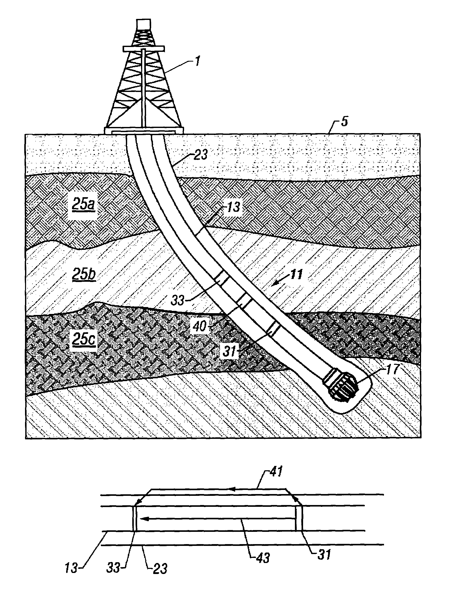
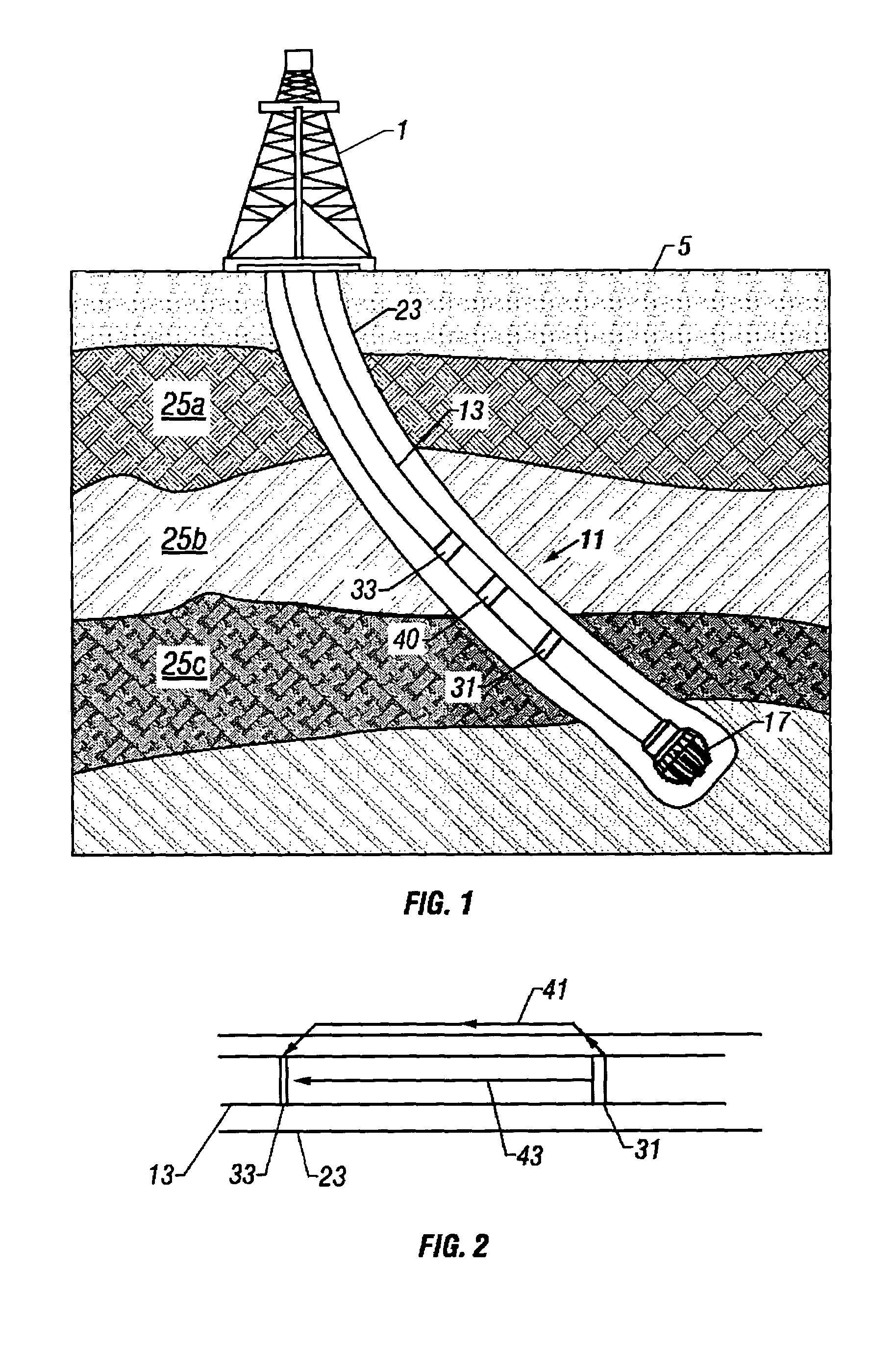
[0037]The present invention provides a system and method for attenuating acoustic waves in a down hole tool that is being used to obtain information about subsurface formations, some of which are believed to be holding hydrocarbon deposits. FIG. 1 is a schematic illustration of the use of a Measurement-While-Drilling (MWD) apparatus while drilling a well. At the surface of the earth 5 a drilling rig 1 is used to drill a borehole 23 through subterranean formations 25a, 25b, 25c etc. Those versed in the art would know that a drillship or a platform could be used to drill a borehole into subterranean formations covered by a body of water. A drilling tubular 13, that could be made of drill pipes or coiled tubing is used to rotate a drillbit 17 at the bottom, the rotating action of the drillbit and axial pressure carving out the borehole. When coiled tubing is used for the drilling tubular, a drilling motor (not shown) is used to impart the necessary rotary motion to the drillbit.

[0038]A...


PUM


Abstract

An apparatus for performing acoustic investigations while drilling a borehole in a subsurface geological formation comprises a longitudinally extending assembly conveyed in the borehole on a drilling tubular. The assembly and the drilling tubular have a drilling fluid flowing through a longitudinally extending passage therein. An acoustic transmitter is supported by the assembly. The transmitter generates acoustic signals in the assembly, the borehole and the subsurface formation. An acoustic receiver is spaced apart from the transmitter and receive the acoustic signals. An attenuator is located in the assembly between the acoustic transmitter and the acoustic receiver for attenuating the acoustic signals in the assembly within a predetermined frequency range. The attenuator comprises a tubular element of a composite material having a substantially cylindrical outer surface. The outer surface has a plurality of spaced apart masses having a predetermined spacing, mass and length firmly attached thereto.

Description

CROSS-REFERENCES TO RELATED APPLICATIONS[0001]The present application is a Continuation-in-Part of U.S. patent application Ser. No. 10 / 044,330 filed on Jan. 10, 2002, now issued U.S. Pat. No. 6,915,875 issued on Jul. 12, 2005, which is a Continuation-in-Part of U.S. patent application Ser. No. 09 / 583,258 filed on May 31, 2000, now issued U.S. Pat. No. 6,615,949 B1, issued on Sep. 9, 2003, that claims priority from and is based upon United States Provisional Patent Application Ser. No. 60 / 137,388 filed on Jun. 3, 1999. Each of the above referenced applications and issued patent are incorporated herein by reference.BACKGROUND OF THE INVENTION[0002]1. Field of the Invention[0003]The present invention pertains to logging while drilling apparatus and more particularly to acoustic logging while drilling apparatus and attenuation of acoustic pulses that travel parallel to the direction of drilling.[0004]2. Related Prior Art[0005]To obtain hydrocarbons such as oil and gas, wells or wellbore...

Claims


Application Information

Patent Timeline
Patent Type & Authority Patents(United States)
IPC IPC(8): G01V1/40G01V1/44G01V1/52
CPCG01V1/523G01V1/52
Inventor DUBINSKY, VLADIMIRBOLSHAKOV, ALEXEI
Owner BAKER HUGHES HLDG LLC
Why Eureka
Try Eureka