Catadioptric light distribution system

a distribution system and catadioptric technology, applied in the direction of semiconductor devices for light sources, fixed installations, lighting and heating apparatus, etc., can solve the problems of not being able to culminate all of the light emitted by a conventional optical system, the distribution system illustrated in kondo et al. is not very effective in collimating the light from an led into an effective beam

Inactive Publication Date: 2006-04-18
GM GLOBAL TECH OPERATIONS LLC
View PDF12 Cites 55 Cited by
  • Summary
  • Abstract
  • Description
  • Claims
  • Application Information

AI Technical Summary

Problems solved by technology

Originally, LEDs were quite small and limited in their capacity to produce light.
Unfortunately, conventional optical systems cannot culminate all of the light emitted by a Lambertian LED because of the wide spread of light emitted by and physical constraints of a Lambertian LED.
However, the various light distribution systems illustrated in Kondo et al. are not very effective in collimating the light from an LED into an effective beam.

Method used


Image

  • Catadioptric light distribution system
  • Catadioptric light distribution system
  • Catadioptric light distribution system

Examples


Embodiment Construction

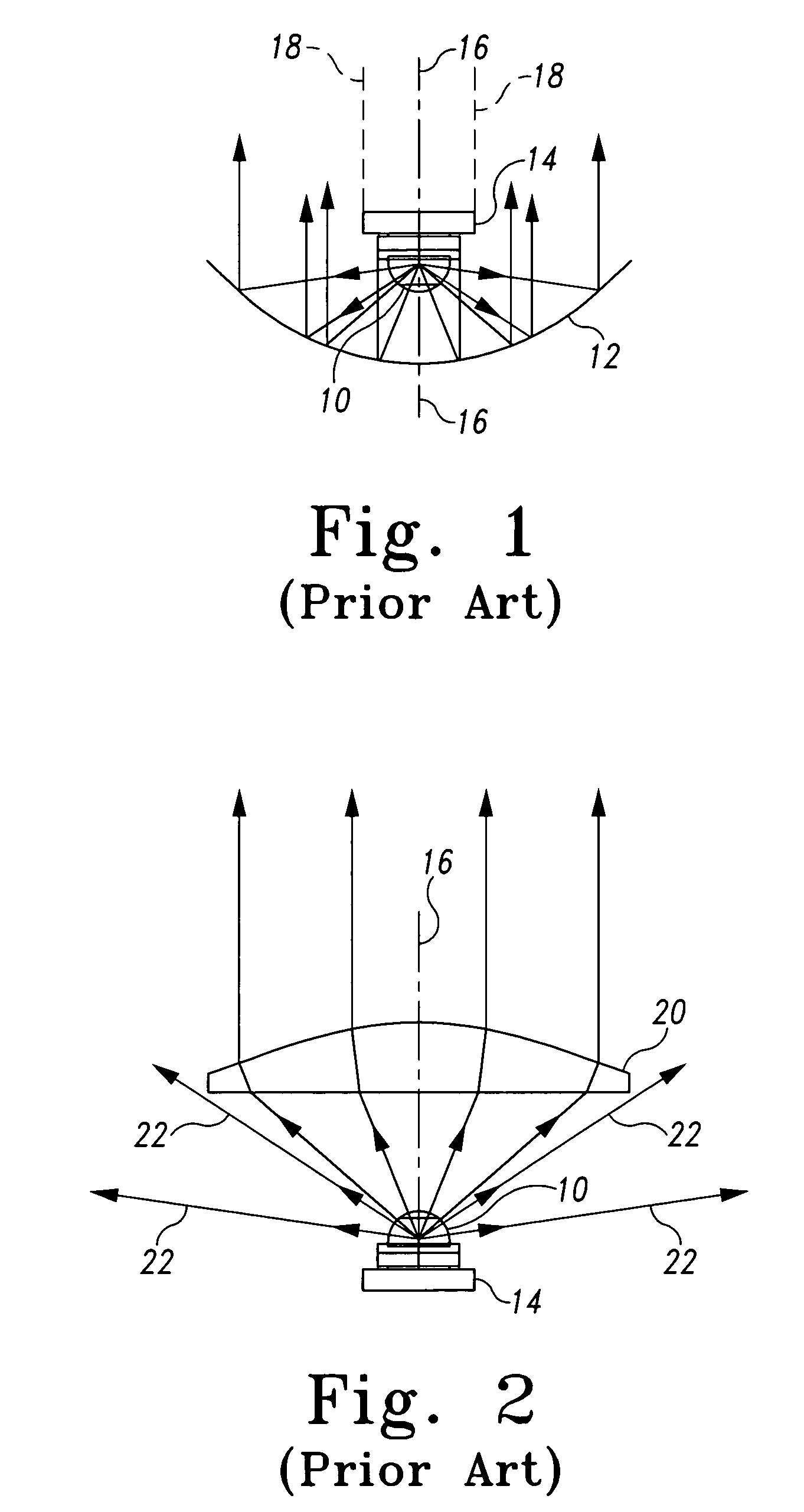
[0014]FIG. 1 discloses a prior art system which uses a Lambertian LED 10 and a parabolic reflector 12. Because of the heat generated by a LED, the LED includes a heat sink 14 on the back of the LED. The parabolic reflector 12 is configured to culminate light generated at the focal point of the paraboloid and culminate that light outwardly. The LED is placed at the focal point of the parabolic reflector and it is facing the parabolic reflector 12 and aligned so that the optical axis of the LED and the center axis of the parabola 16 are aligned. Because the Lambertian LED emits light 360° around the optical axis and from 0 to about 90° as measured from the optical axis, a hemispherical light distribution pattern is produced. Unfortunately, because of the heat sink 14 mounted on the base of the Lambertian LED 10, light reflected by the center of the parabolic reflector 12 is essentially blocked by the heat sink 14 so that a dark shadow column as depicted by the dotted lines 18, is prod...


PUM


Abstract

A Catadioptric Light Distribution System that collects and collimates the hemispherical pattern of light emitted by a Lambertian light emitting diode (LED) into a collimated beam directed essentially parallel to the optical axis of the LED. The system comprises a circular condensing lens having a center axis that is aligned with the optical axis of the LED parabolic reflector having circular opening formed therethrough which is centered on the center axis of the parabolic reflector and a double bounce mirror. The light reflected and culminated by the parabolic reflector is directed onto the circular annular double bounce mirror so that this light is collimated in an annular beam which passes around the edge of the condensing lens.

Description

BACKGROUND OF INVENTION[0001]1. Field of the Invention[0002]The present invention relates to a catadioptric light distribution system for collimating a hemispherical pattern of light distributed by a lambertian light emitting diode into a collimated beam of light directed essentially along the optical axis of the LED. More particularly, the present system relates to a catadioptric light distribution system that can be used to culminate a beam light from an LED for automotive lighting purposes.[0003]2. Detailed Description of the Prior Art[0004]Light emitting diodes, commonly called LEDs, are well known in the art. LEDs are light producing devices that illuminate solely as a result of electrons moving in a semi-conductor material. Consequently, LEDs are advantageous as compared to filament type bulbs because an LED has no filament to burn out. Consequently, LEDs generally have a life as long as a standard transistor, and as a result have been utilized in a variety of different device...

Claims


Application Information

Patent Timeline
Patent Type & Authority Patents(United States)
IPC IPC(8): F21V7/00F21S8/10F21V13/12
CPCF21S48/215F21S48/23F21V13/12F21V7/0025F21Y2101/02F21Y2115/10F21S43/14F21S43/30
Inventor FINCH, TIMOTHY S.
Owner GM GLOBAL TECH OPERATIONS LLC
Why Eureka
Try Eureka