Variable reluctance-type resolver

a resolver and resistance type technology, applied in the field of variable resistance type resolvers, can solve the problems of poor detection accuracy, difficult detection of resistance variation, leakage of magnetic flux, etc., and achieve the effect of low or poor detection accuracy

Inactive Publication Date: 2006-04-18
TOYODA MASCH WORKS LTD +2
View PDF4 Cites 6 Cited by
  • Summary
  • Abstract
  • Description
  • Claims
  • Application Information

AI Technical Summary

Benefits of technology

[0009]The present invention has been made in view of the above circumstances, and intends to provide the variable reluctance-type resolver which does not suffer from low or poor detecting accuracy resulted from the leak of magnetic flux from the rotor to the stopper, and which can fix the rotor to the rotate shaft in cheaper way.
[0013]Despite the stopper made of the magnetic material is used, the magnetic flux generated by the excite coil flows from the inner peripheral surface of the magnetic pole to the outer peripheral surface of the rotor. It further flows from the outer peripheral surface of the rotor to the magnetic pole. Thus, magnetic flux leakage is prevented without deteriorating the detecting accuracy cheaply.
[0016]The distance from the magnetic pole of the stator to the outer peripheral surface of the stopper is larger than that between the magnetic pole of the stator and the outer peripheral surface of the rotor. For this reason, the sufficient magnetic resistance for preventing the magnetic flux leakage can be secured. In addition, the annular stopper can be worked easily and can be assembled to the rotate shaft easily, which contributes to further decrease of the cost.
[0018]Leakage of magnetic flux can be prevented more securely, and the rotor can be fixed to the rotate shaft securely in the axial direction with maintaining strength and rigidity of the stopper.
[0019]When outer diameter of the stopper diameter of the rotor is equal to or smaller than 97.4% or 96.4% of the valley diameter, the magnetic flux leakage preventing effect is further increased. However, for maintaining the strength and rigidity of the stopper, the outer diameter is at least 88% of the valley diameter.
[0021](5) Additionally, following modifications can be adopted. The stopper and the rotor can be constructed separately or integrally. When they are separated, the stopper can be pressed in, adhered to or screwed with the rotate shaft. When they are integral, the stopper and the rotor can be formed by accumulating the silicone steel plates, or by cutting and grinding the magnetic material such as iron steel. The numbers of members can be decreased, the working and assembling becomes easily. Thus, further decrease of the cost can be performed. In both of the stopper and the rotor being separate and integral, the stopper can be disposed at only one lateral side of the rotor, or at both sides thereof.

Problems solved by technology

In the above variable reluctance-type resolver, when a member made of a magnetic material is disposed near to the rotor, there is fear that a part of the magnetic flux generated by the excite coil flows into a magnetic member disposed near to the rotor.
Thus, leakage of magnetic flux may occur.
If the magnetic flux leakage occurs, the output signal is not inducted (induced) in the detect coil of the stator accurately, which makes accurate detection of the reluctance variation difficult.
In this way, the detect accuracy may be deteriorated.
However, the non-magnetic member more expensive than the magnetic material increases the cost.

Method used


Image

  • Variable reluctance-type resolver
  • Variable reluctance-type resolver
  • Variable reluctance-type resolver

Examples


Embodiment Construction

[0027]In the following, preferable embodiment of the present invention will be explained with reference to attached drawings. However, it is noted that the present invention should not be limited to this embodiment.

(Construction)

[0028]In this embodiment, the present invention is applied to an electrical power steering apparatus of a vehicle. As well known, in the power steering apparatus, a steering torque applied to a steering wheel is detected, and required steering assist torque corresponding to the steering torque is generated by the motor to assist the steering. The power steering apparatus comprises a steering wheel, torque sensor for detecting the steering torque, motor for generating the steering assist torque, control device for controlling the motor based on information from the torque sensor, and torque transmit mechanism for transmitting torque from the steering wheel and the motor to the steered wheel (tire).

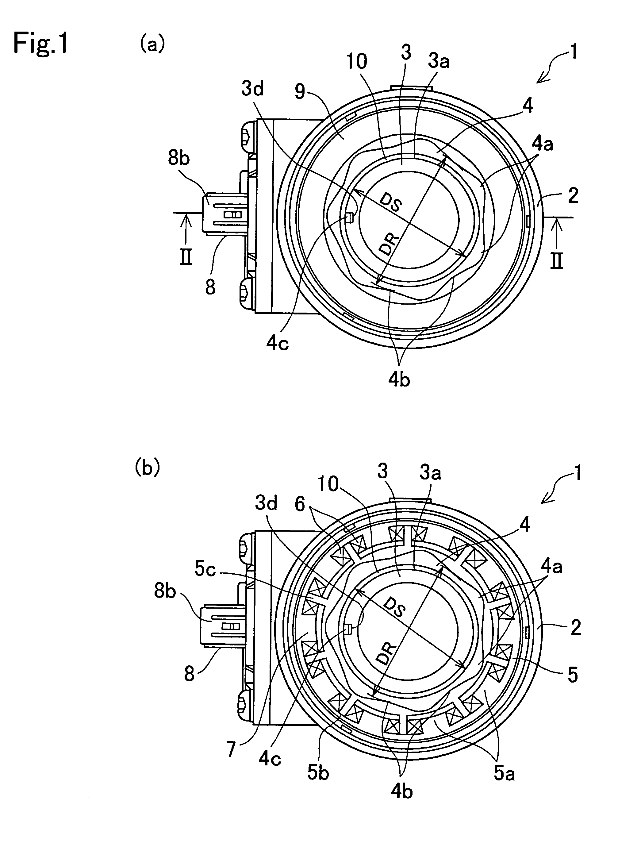
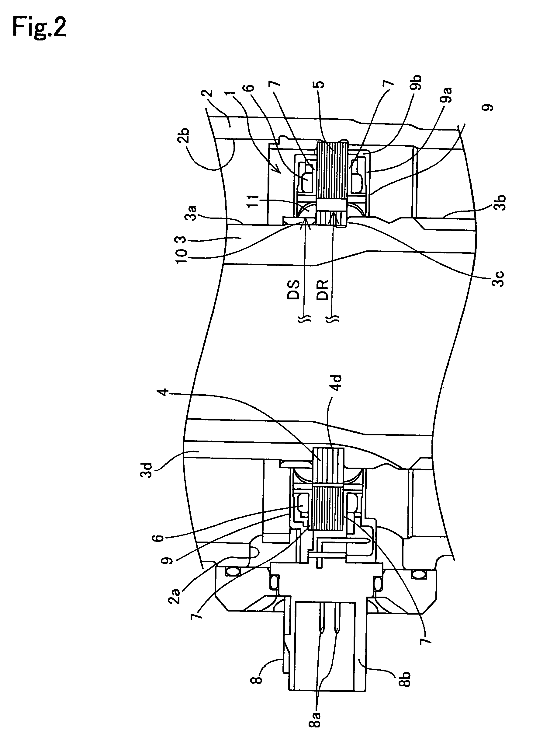
[0029]The variable reluctance-type resolver (referred simply “...


PUM


Abstract

A variable reluctance-type resolver which does not deteriorate detecting accuracy, and which can fix the rotor to the rotate shaft cheaply is comprised of a stator 5 on which coils 6 are wound, a rotor provided with protrude poles 4a and an annular stopper 10 made of magnetic material. An outer diameter DS of the stopper 10 is selected to be smaller than a valley diameter DR of the rotor 4. Leakage of the magnetic flux from the stator to the stopper is prevented, and the stopper made of the magnetic material can fix the rotor in cheaper way.

Description

CROSS-REFERENCE TO RELATED APPLICATION[0001]This application based on and claims priority under 35 U.S.C. 119 to Japanese Patent Application No. 2003-207742 filed on Aug. 18, 2003, the entire contents of which are incorporated herein by reference.BACKGROUND OF THE INVENTION[0002]1. Field of the Invention[0003]The present invention relates to a variable reluctance-type resolver.[0004]2. Description of the Related Art[0005]As a rotation detecting sensor, resolver including coils has been known. For example, variable reluctance-type resolver disclosed in the Japanese Patent Laid-open Publication No. 2002-168 652 comprises a stator on which an excite coil (winding), first detect coil (winding) and second detect coil (winding) are wound, and a rotor having four arch-shaped induct portions protruded radially outwardly.[0006]When the rotor rotates, gap between the induct portions of the rotor and the magnetic poles of the stator on which the coils are wound varies. This gap variation is de...

Claims


Application Information

Patent Timeline
Patent Type & Authority Patents(United States)
IPC IPC(8): G01B7/30G01D5/20H02K24/00G01D5/245
CPCG01D5/2046
Inventor ANDO, KATSUAKITAKAHASHI, HIROYUKI
Owner TOYODA MASCH WORKS LTD
Why Eureka
Try Eureka