Method of fixing terminal fitting components to each other and terminal fitting

a technology of terminal fittings and components, applied in the direction of multi-conductor cable end pieces, coupling contact members, coupling device connections, etc., can solve the problems of increasing the cost of the terminal fitting itself, so as to reduce the electric resistance between the terminal fitting components fixed to each other

Active Publication Date: 2007-03-01
YAZAKI CORP
View PDF13 Cites 10 Cited by
  • Summary
  • Abstract
  • Description
  • Claims
  • Application Information

AI Technical Summary

Benefits of technology

[0037] With the construction described above, the enlarged part more securely adheres to the tapered surface. Therefore, an electric resistance between the terminal fitting components fixed to each other can

Problems solved by technology

However, in such a case, a mold for forming the first electric contacting part by bending is forced to be complicated, causing the cost of the terminal fitting itself to increase.
However, in such a case, a structure of said one of the first and second terminal fitting components having the spring piece is forc

Method used


Image

  • Method of fixing terminal fitting components to each other and terminal fitting
  • Method of fixing terminal fitting components to each other and terminal fitting
  • Method of fixing terminal fitting components to each other and terminal fitting

Examples


Embodiment Construction

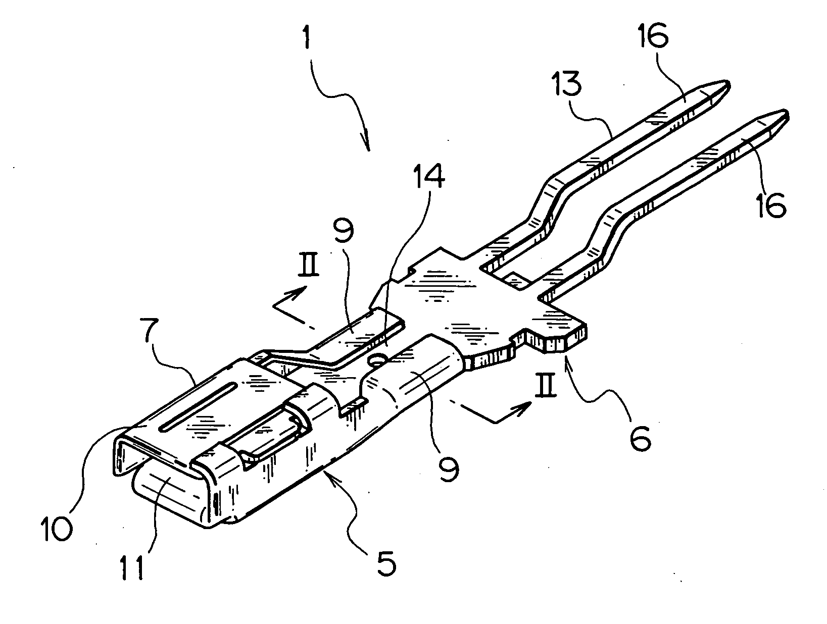
[0059] In the following, a terminal fitting according to the first preferred embodiment of the present invention is explained with reference to FIGS. 1-7. A terminal fitting 1 shown in FIG. 1 and the other figures constructs a connector (not shown in the figure).

[0060] The connector includes a connector housing made of electrically insulating synthetic resin and the terminal fitting 1. The connector housing is formed in a box-shape and has many terminal-receiving chambers for receiving the terminal fittings 1. The connector housing is attached to a printed wiring board and fits to a connector housing of a mating connector.

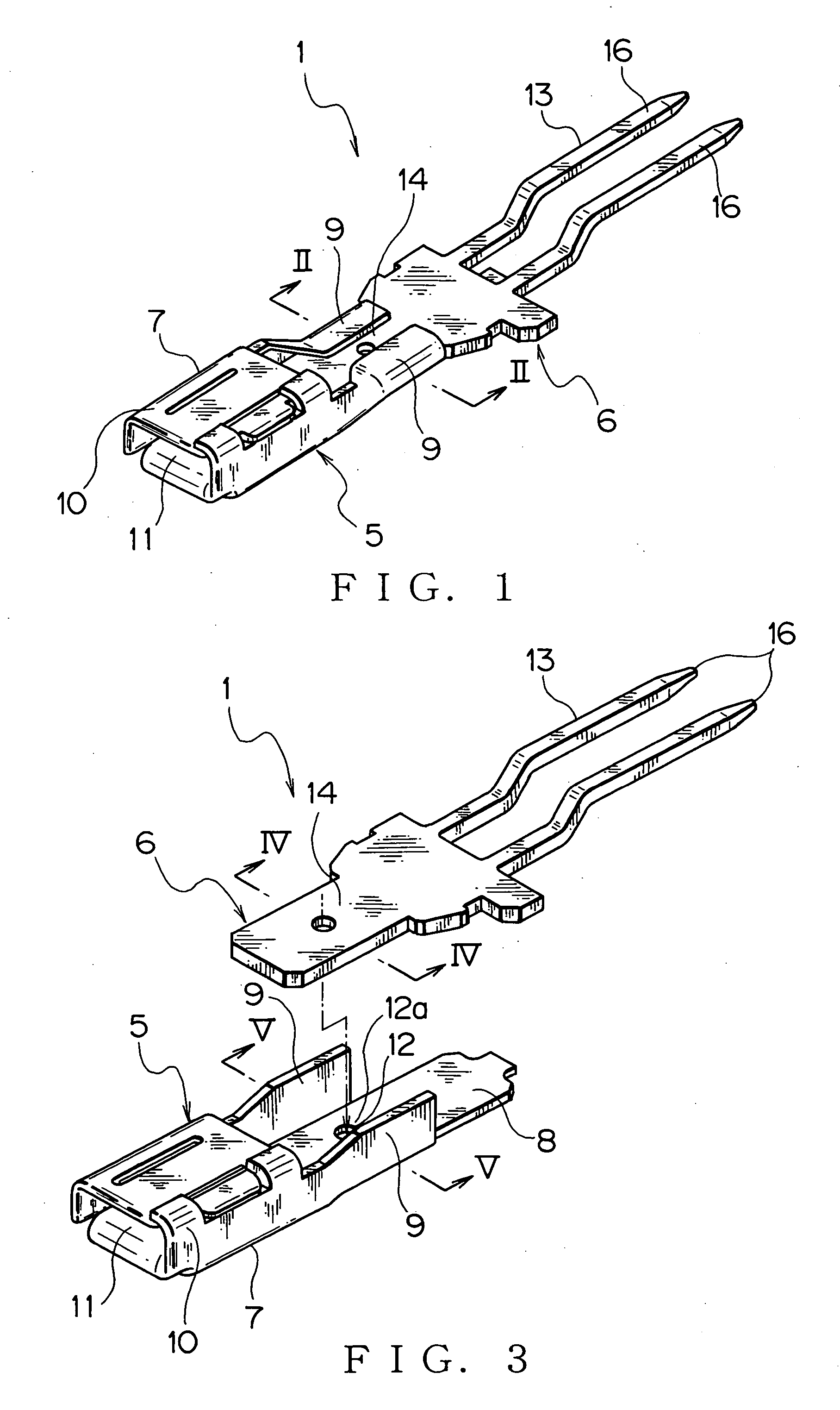
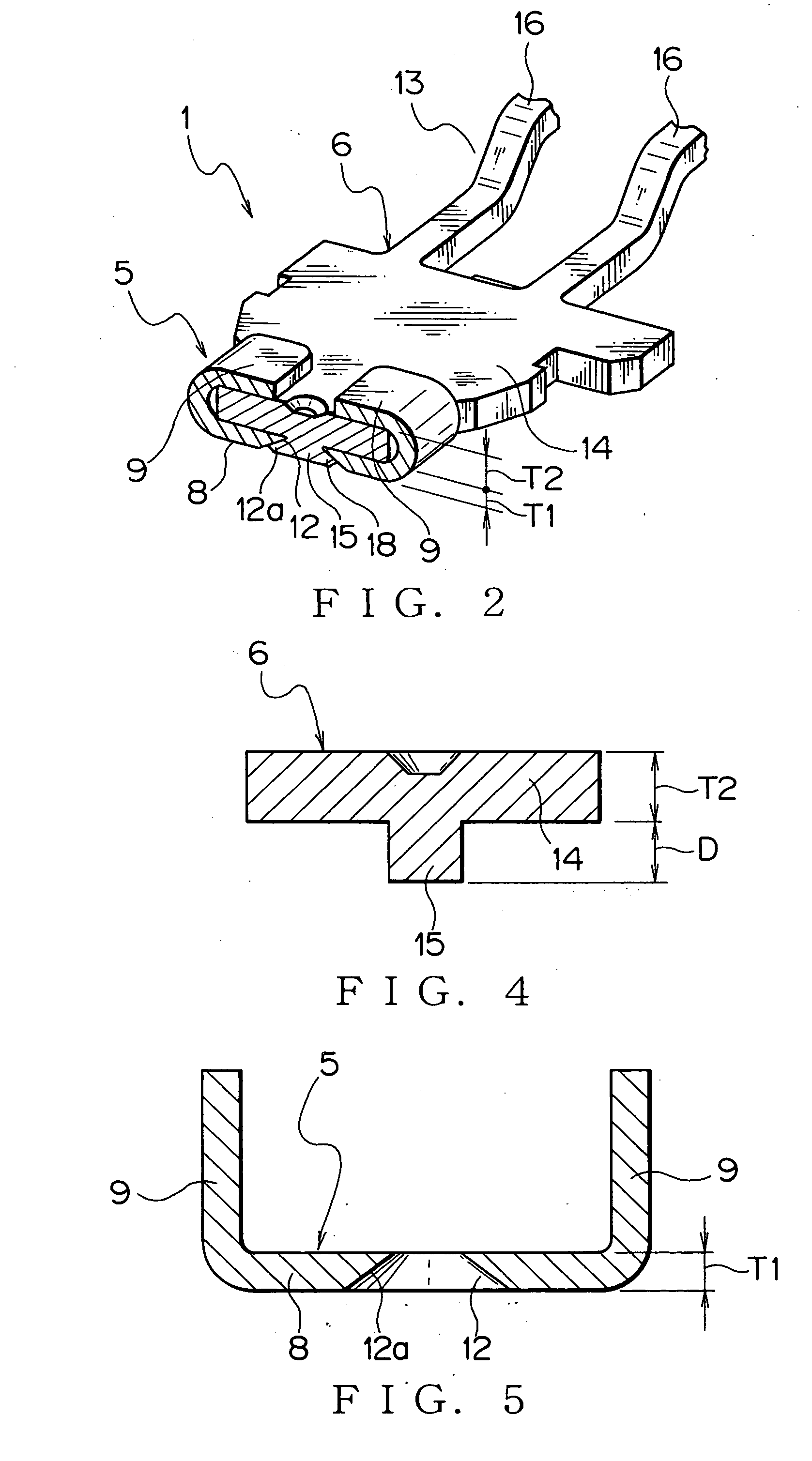
[0061] As shown in FIGS. 1 and 2, the terminal fitting 1 includes a first terminal fitting component 5 and a second terminal fitting component 6.

[0062] The terminal fitting 1 is made of electrically conductive metal plate and includes integrally a first electric contact part 7, first flat plate 8 and a pair of caulking pieces 9 as shown in FIG. 3. The first elec...


PUM


Abstract

A terminal fitting includes first and second terminal fitting components. The first terminal fitting component includes a first flat plate having a through hole and caulking pieces. The caulking pieces stand up from both edges in the width direction of the first flat plate. The second terminal fitting component includes a second flat plate having a projection. The projection is inserted in the through hole, an end part of the projection is crushed, and the second flat plate is caulked with the caulking pieces so that the first and second terminal fitting components are fixed to each other, thereby obtaining the terminal fitting.

Description

BACKGROUND OF THE INVENTION [0001] (1) Field of the Invention [0002] The present invention relates to a method of fixing terminal fitting components to each other and a terminal fitting which composes a wiring harness to be mounted on a motor vehicle and so on. [0003] (2) Description of the Related Art [0004] Various electronic instruments are mounted on a motor vehicle as a mobile unit. The motor vehicle is equipped with a wiring harness to transmit electric power and control signals to the electronic instruments. The wiring harness includes a plurality of electric wires and connectors. The electric wire is the so-called coated electric wire, which includes an electrically conductive core wire and an electrically insulating coating that coats the core wire. [0005] The connector includes a terminal fitting and connector housing. The terminal fitting consists of an electrically conductive metal plate. The connector housing is made of electrically insulating synthetic resin and formed...

Claims


Application Information

Patent Timeline
IPC IPC(8): H01R13/02
CPCH01R13/113H01R13/055
Inventor UCHIDA, JUNSAMEJIMA, MASAKUNISHIMIZU, ISANORISUZUKI, TAMIO
Owner YAZAKI CORP
Why Eureka
Try Eureka