Motor and compressor with the same

Active Publication Date: 2010-11-18
KOBELCO COMPRESSORS CORP
View PDF38 Cites 3 Cited by
  • Summary
  • Abstract
  • Description
  • Claims
  • Application Information

AI Technical Summary

Benefits of technology

[0007]In consideration of the problem above, it is an object of the present invention to provide a motor capable of reducing electric resistance between a plurality of electric wires from the motor side and a terminal rod to be connected to a power source, and strongly combining the electric wires and the terminal rod, and a screw compressor with this motor.
[0009]According to this configuration, the one ends of a plurality of the electric wires are connected to the motor stator inside the motor casing, the other ends thereof are inserted into the concave part of the crimping portion of the terminal rod, and the outer surface of the crimping portion is pressurized, so that the other ends of a plurality of the electric wires can be fixed to the crimping portion. Since a plurality of the electric wires and the concave part are in uniform contact with each other by crimping, it is possible to reduce the electric resistance between a plurality of the electric wires and the terminal rod. Since the air between the electric wires and the concave part of the terminal rod can be moved through the communication part, it is possible to release pressure of the concave part so as to prevent the electric wires inserted into the concave part from moving in the direction of dropping off the concave part. Therefore, the electric resistance between the electric wires and the terminal rod is not increased.
[0010]Preferably, the seal portion has a diameter gradually reduced in the direction from the depression toward the exterior of the motor casing, and the seal member is put on the terminal rod on the opposite side of the flange portion with respect to the crimping portion so as to be disposed along the seal portion. According to this configuration, the seal portion can be easily processed, and the seal member is easily disposed along the seal portion.
[0011]Preferably, the terminal base is made of polyphenylene sulfide. According to this configuration, it is possible to have corrosion resistance against gas in the interior of the motor casing, and pressure resistance against pressure in the interior of the motor casing.
[0013]Preferably, each of the electric wires is provided with a coat made of fluorine resin. According to this configuration, it is possible to more surely prevent damage and corrosion of the electric wires.

Problems solved by technology

However, with this method, the aluminum wires and the terminal main body are insufficiently combined at an inner circumference on the radially opposite side of the cutout portion of the terminal main body, so that conductivity is deteriorated.
As a result, there is a possibility that burnout of the motor is caused.
Thereby, the electric wire is moved in the direction of dropping off the wire insertion hole of the connection terminal, so as to cause a problem that contact resistance is increased.

Method used


Image

  • Motor and compressor with the same
  • Motor and compressor with the same
  • Motor and compressor with the same

Examples


Embodiment Construction

[0023]Hereinafter, an embodiment of the present invention will be described in accordance with the drawings.

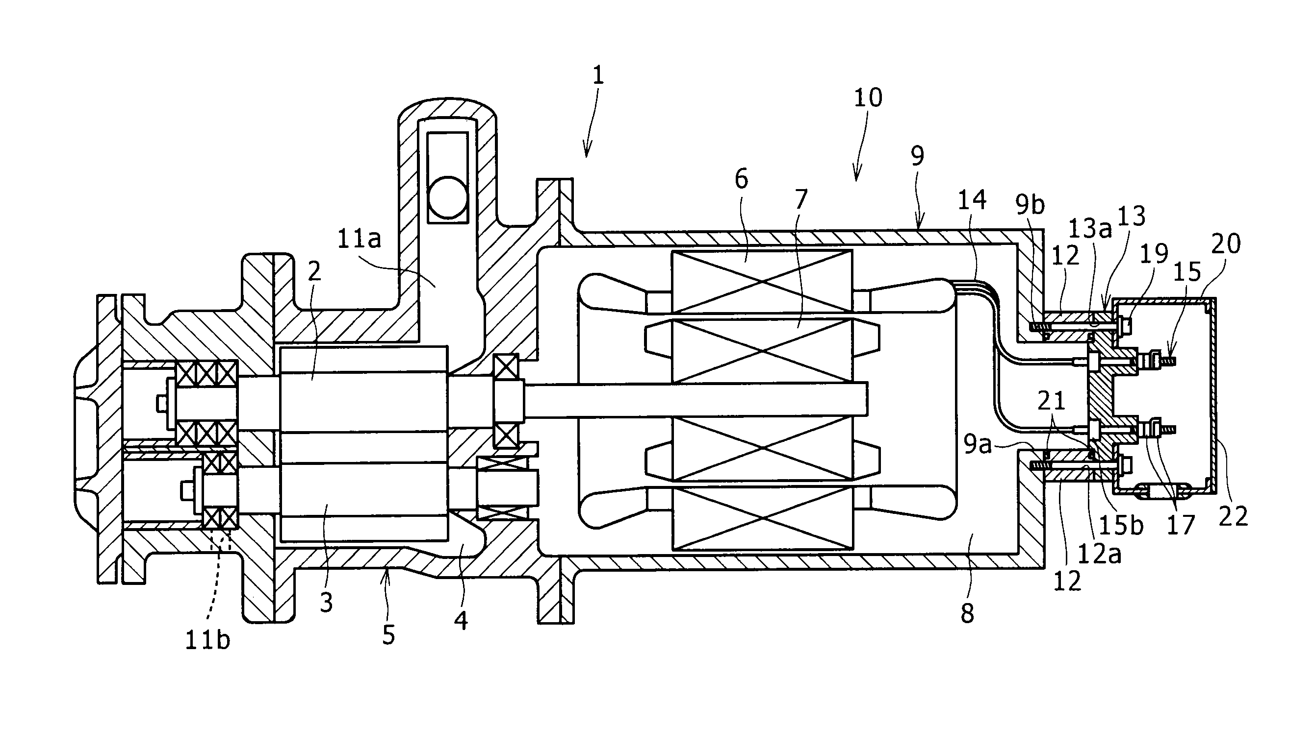
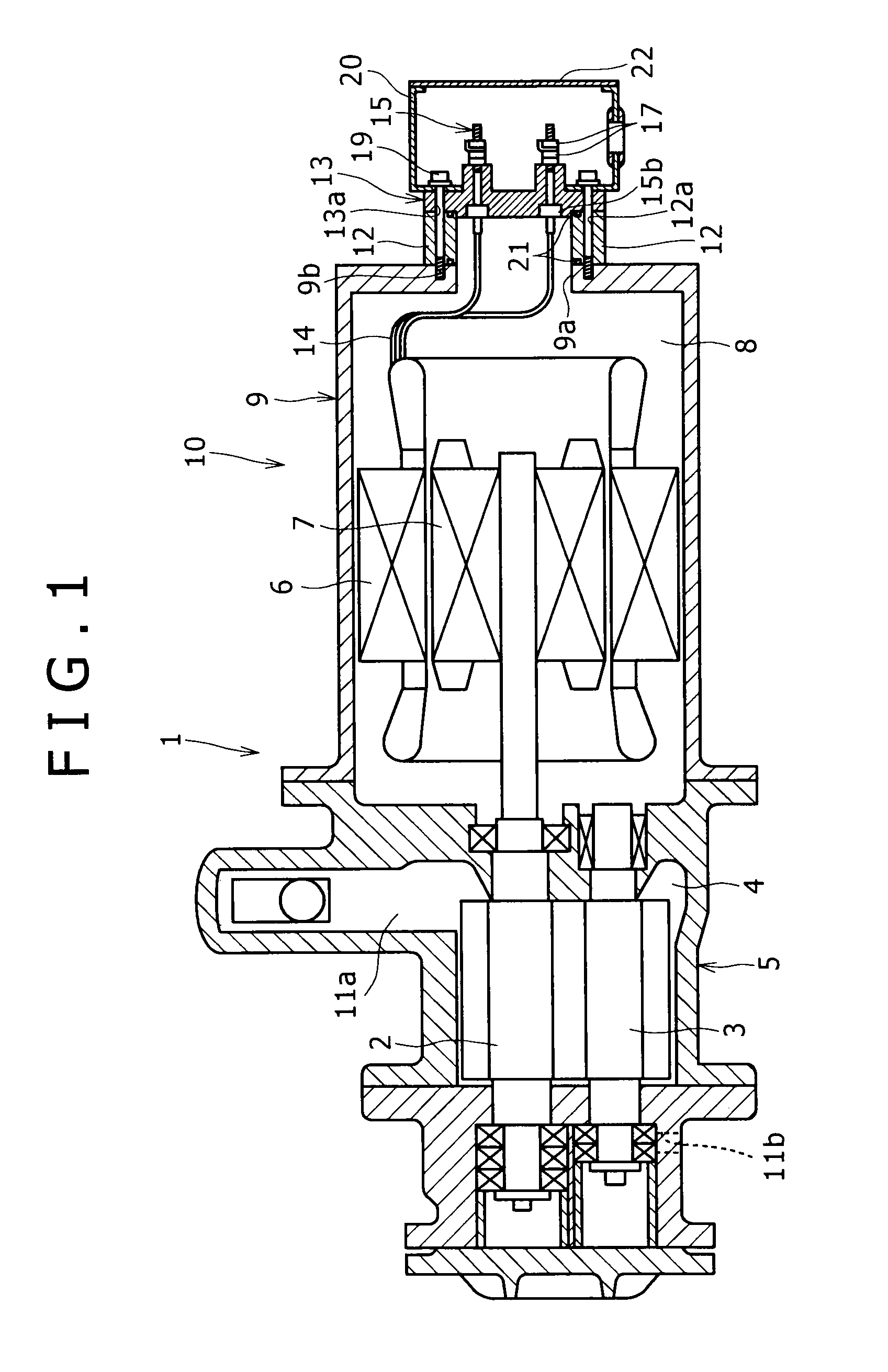
[0024]FIG. 1 shows a screw compressor 1 according to one embodiment of the present invention. In the screw compressor 1, a rotor casing 5 forming a rotor chamber 4 accommodating screw rotors (a male rotor 2 and a female rotor 3) meshed with each other is integrally connected to a motor casing 9 forming a motor chamber 8 accommodating a motor stator 6 and a motor rotor 7 sharing an axis with the male rotor 2. In FIG. 1, a motor 10 is a part on the right side on the paper relative to a connection part between the rotor casing 5 and the motor casing 9.

[0025]The screw rotors 2, 3 are rotated by rotational force of the motor rotor 7, so as to suction and compress a refrigerant (ammonia gas) from a suction flow passage 11a, and discharge the compressed refrigerant from a discharge flow passage 11b.

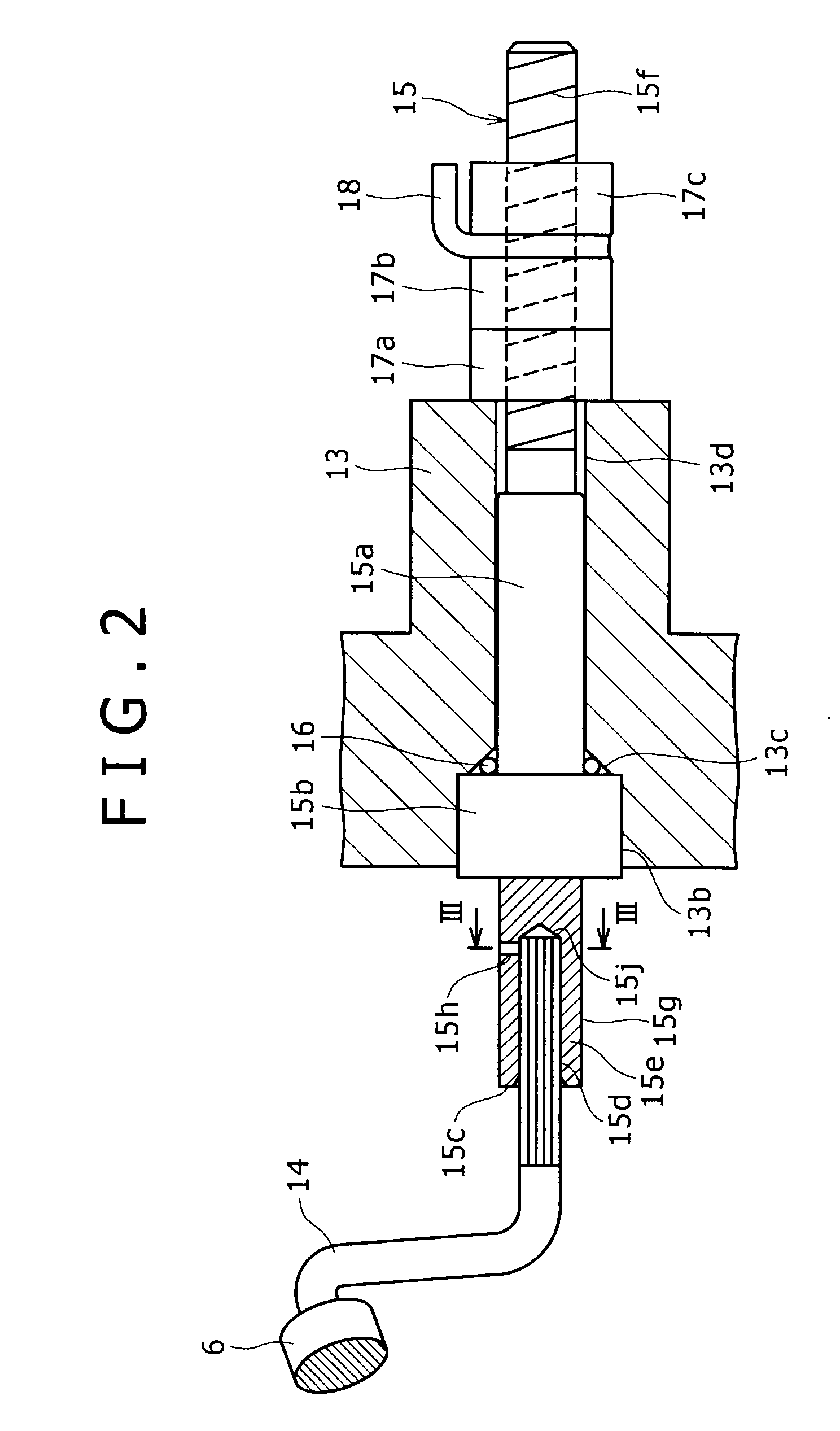
[0026]An opening part 9a is provided on an end surface of the motor casing 9 on the o...


PUM


Abstract

In a motor, one ends of a plurality of electric wires with the other ends connected to the motor side are connected to a terminal rod, and the terminal rod is exposed to the exterior of a motor casing via a terminal base. The terminal rod is provided with a flange portion and a crimping portion. A concave part is formed on an end surface of the crimping portion, and a communication part providing communication between an outer surface and the concave part is formed. The terminal base is provided with a depression to be fitted to the flange portion of the terminal rod, a seal portion having a diameter reduced from the depression, and a through portion passing from the seal portion through to the exterior of the motor casing. A seal member is put on the terminal rod. In a state that the electric wires are inserted into the concave part of the crimping portion, the outer surface of the crimping portion is pressurized, so that the electric wires are fixed to the crimping portion. With such a configuration, it is possible to reduce electric resistance between the electric wires from the motor side and the terminal rod and strongly combine the electric wires and the terminal rod.

Description

BACKGROUND OF THE INVENTION[0001]1. Field of the Invention[0002]The present invention relates to a motor suitable for a compressor, and a compressor with the motor.[0003]2. Description of the Related Art[0004]Conventionally, a core wire formed by twisting a plurality of aluminum wires by predetermined length from end surfaces thereof is used for a motor of a compressor. In order to connect the core wire to a terminal of the compressor, Japanese Patent Laid-Open No. 1997-180770 discloses a method of providing a fitting hole extending in the axial direction in a main body of a rod shape conducting terminal made of aluminum, forming a cutout portion communicating with the fitting hole in a part of an outer circumference thereof, inserting a core wire into the fitting hole, heating from the upper side of the cutout portion so as to melt at least an edge of the cutout portion, and fixing and connecting the core wire and the main body by the welding.[0005]However, with this method, the al...

Claims


Application Information

Patent Timeline
IPC IPC(8): F04B35/04H02K11/00
CPCH02K3/46H02K3/12H02K5/225
Inventor TSUBOI, NOBORU
Owner KOBELCO COMPRESSORS CORP
Why Eureka
Try Eureka