Float valve device

Inactive Publication Date: 2006-04-25
PIOLAX CO LTD
View PDF4 Cites 19 Cited by
  • Summary
  • Abstract
  • Description
  • Claims
  • Application Information

AI Technical Summary

Benefits of technology

[0016]According to the third aspect, the brim formed on the float valve member is arranged in the wider rib spacing on the inner circumference of the valve case so that the angle of the float valve member with respect to the valve case is regulated. In th

Problems solved by technology

However, the fuel cutoff valve is not provided with the rotation stop means for stopping the rotation of the float body relative to the case body.
However, no consideration has heretofore been taken i

Method used


Image

  • Float valve device
  • Float valve device
  • Float valve device

Examples


Embodiment Construction

[0027]An embodiment of the invention will be described with reference to the accompanying drawings.

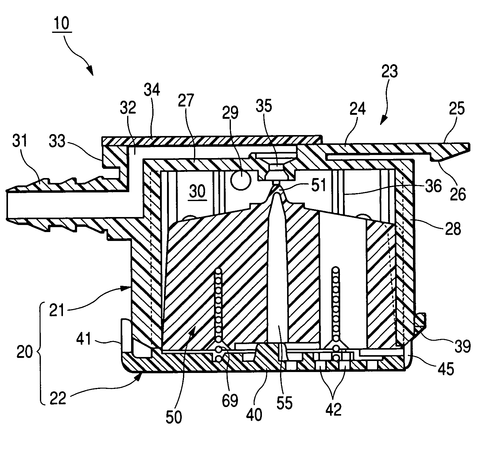
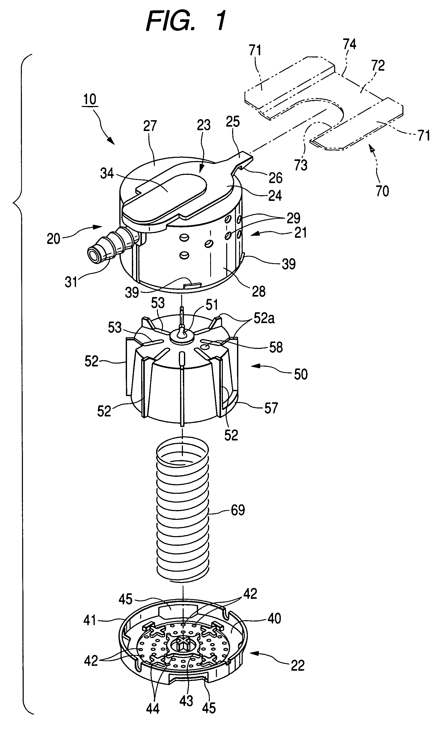
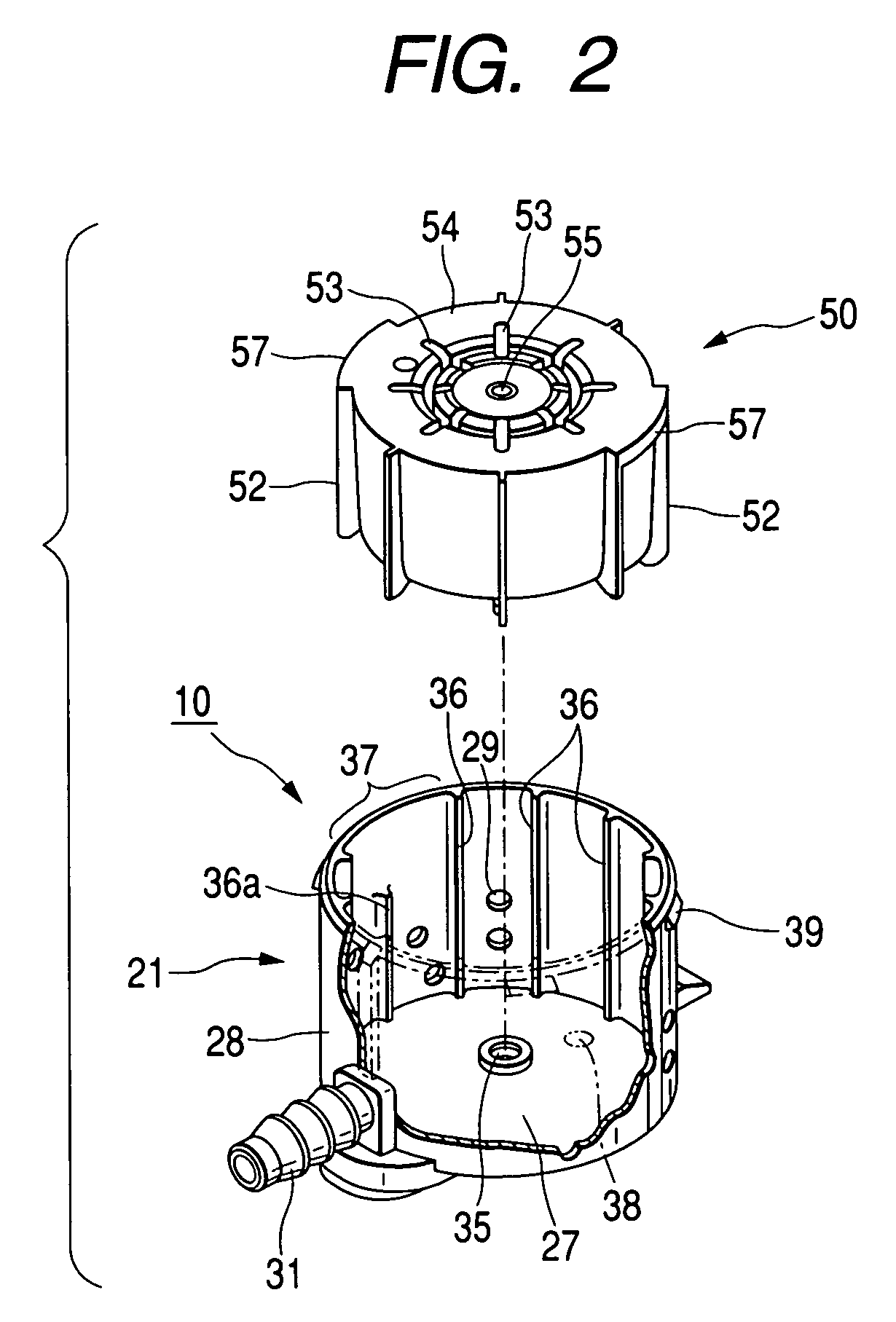
[0028]FIG. 1 to FIG. 9B show one embodiment of the float valve device according to the invention. FIG. 1 is an exploded perspective view of a float valve device according to one embodiment of the invention; FIG. 2 is a perspective view showing the state of the float valve device, in which a float valve member is to be inserted into a valve case body; FIG. 3A is a longitudinal section showing the state of the float valve device, in which the float valve member is inserted in the valve case body, FIG. 3B is a section taken along line I—I of FIG. 3A; FIG. 4A is a top plan view of the float valve member; FIG. 4B is a section taken along line II—II of FIG. 4A; FIG. 4C is a section taken along line III—III of FIG. 4B; FIG. 5 is a longitudinal section of the float valve device; FIG. 6 is an explanatory view showing the state, in which the valve of the float valve device arranged in a fuel tan...


PUM


Abstract

An allowable angle of a float valve member with respect to a valve case is so set that a deformed direction, as caused by a gate position at a injection molding time, of a inner circumference of a communication hole of the valve case with respect to a roundness and a deformed direction, as caused by a gate position at a injection molding time, of an outer circumference of a crest portion of the float valve member with respect to the roundness may be substantially aligned. Between the valve case and the float valve member, there is an interposed angle regulating unit for preventing the angle of the float valve member with respect to the valve case from varying over the allowable angle.

Description

BACKGROUND OF THE INVENTION[0001]1. Field of the Invention[0002]The present invention relates to a float valve device suited for a fuel cutoff valve for preventing a fuel from flowing out of the fuel tank of an automobile when the liquid level of the fuel tank rises.[0003]2. Description of the Related Art[0004]In Japanese Patent No. 3,257,437, for example, a fuel cutoff valve of the kind used in related art systems is disclosed. The fuel cutoff valve includes: a case body forming a valve chamber connected to a communication passage for establishing communication of the inside of a fuel tank with the outside; and a float valve member accommodated in the valve chamber and having a closed portion at its upper portion for opening / closing the communication passage so that it may move upward and downward by increasing / decreasing a buoyancy with a liquid fuel in the fuel tank to flow into and out of the valve chamber thereby to open / close the communication passage with the closed portion. ...

Claims


Application Information

Patent Timeline
IPC IPC(8): F16K24/04B60K15/077F16K24/00
CPCF16K24/042Y10T137/0874Y10T137/3099
Inventor MATSUO, SHINICHIYONEZAWA, KENJI
Owner PIOLAX CO LTD
Why Eureka
Try Eureka