Pressure regulator and method of use

a technology of pressure regulator and pressure regulator, which is applied in the direction of fluid pressure control, process and machine control, instruments, etc., can solve the problems of reducing vehicle fuel economy, wasting fuel, and significantly reducing tire service li

Inactive Publication Date: 2006-04-25
SHENG XIAYANG
View PDF23 Cites 49 Cited by
  • Summary
  • Abstract
  • Description
  • Claims
  • Application Information

AI Technical Summary

Benefits of technology

[0006]The aforementioned need is fulfilled by embodiments of the invention in one or more of the following aspects. In one aspect, the invention relates to a pressure regulator for connecting a pressure source to an inflatable object. The pressure regulator comprises: (a) a hollow casing having a fluid inlet end, a fluid outlet end, and a side wall; (b) a valve system positioned inside the hollow casing; (c) a fluid inlet connected to the valve system, the inlet located at the fluid inlet end of the hollow casing and adaptable for connection to a pressure source; (d) a fluid outlet located at the fluid outlet end of the hollow casing, the outlet adaptable for connection to an inflatable object; (e) a fluid conduit positioned inside the hollow casing between the fluid inlet and the fluid outlet; (f) a pressure-sensing structure attached to the conduit, th

Problems solved by technology

Improperly inflated tires may wear out quickly, waste fuel, and can cause collisions.
Either over-inflated or under-inflated tires may significantly reduce tire service life.
Under-inflated tires often result in reduced vehicle fuel economy.
Most tire inflation methods generally are tedious and involve trial and error.
Since there is no significant pressure head for the pressure charge, this approach takes

Method used


Image

  • Pressure regulator and method of use
  • Pressure regulator and method of use
  • Pressure regulator and method of use

Examples


second embodiment

[0051]Referring to FIGS. 5–7, the pressure regulator comprises a hollow cylindrical casing 15, a ball valve seat 23, a ball valve 25, a ball valve spring 27, a ball valve spring support 29, a conduit 35, a pressure-sensing structure (e.g., an O-ring piston) 45, a spring 55, a spring collar 61, two screws 63, a nut 65, a bellows 75, and a pressure indicator 95.

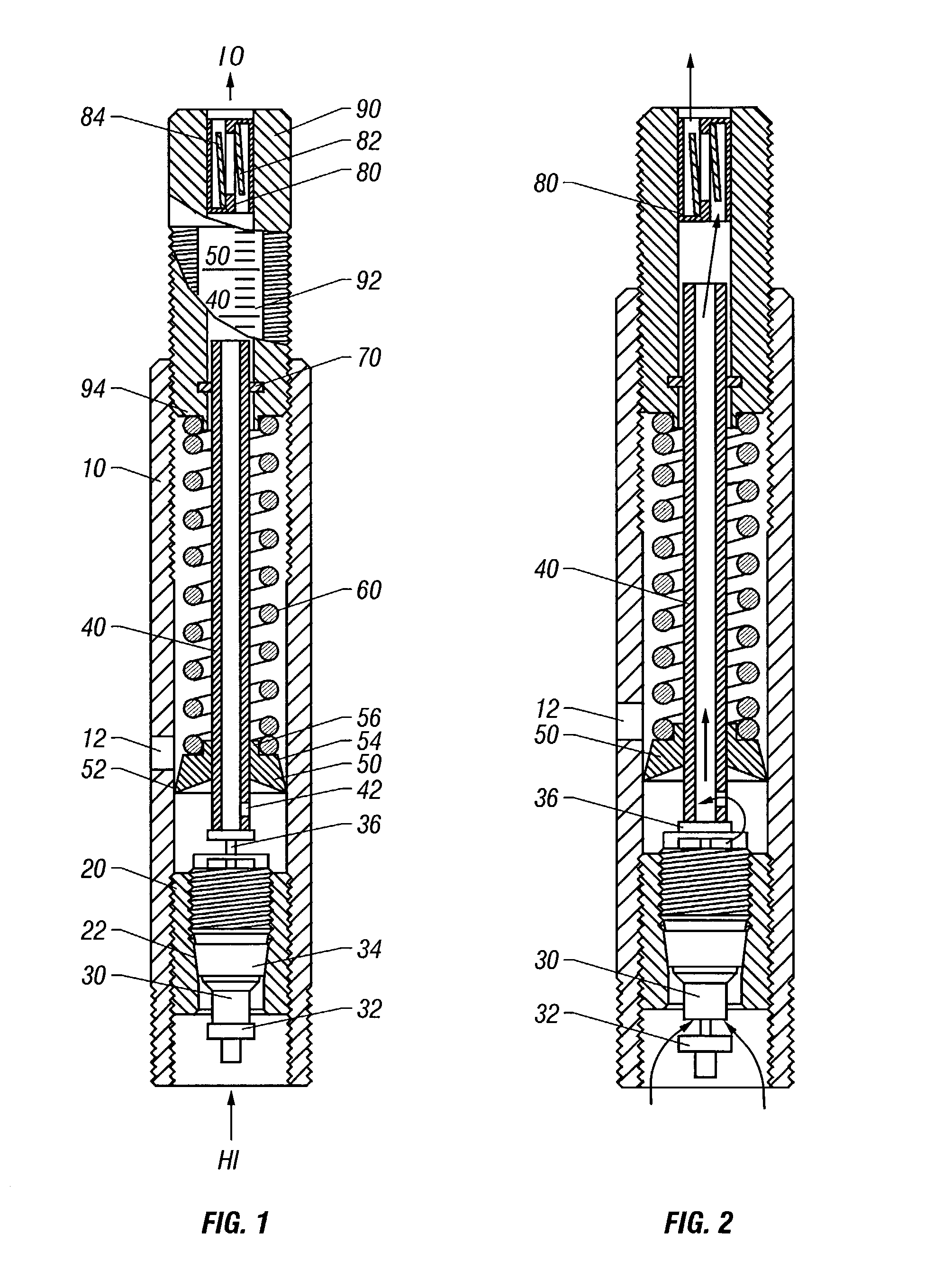
[0052]The hollow cylindrical casing 15 has at least one slot 11 (preferably two slots) on the side wall of the casing 15 in the longitudinal direction (i.e., the lengthwise direction of the hollow casing 15). The casing 15 also has numerical pressure marks 95 on the side wall. The casing 15 further includes inside and outside threads at both ends. One end of the casing 15 provides a fluid inlet from a high pressure source (not shown) designated as “HI,” and the other end of the casing 15 provides a fluid outlet to a low pressure receiving object (not shown) designated as “LO.”

[0053]A valve system is provided by the ball valve s...

first embodiment

[0063]FIGS. 8 and 9 show another embodiment of the invention, which is modified from FIG. 1. First, the audible reed 80 of FIG. 1 is replaced by a visible ball display 200 in this embodiment, which is suited for use in a noisy environment. Second, the valve core 30 of FIG. 1 is replaced by the rubber stopper 300 in this embodiment and the piston system is turned upside down. With this design, the regulator may lose its deflating function, but its valve system is simplified as a piece of rubber stopper. An advantage of this rubber stopper is that it is fixed to the inner wall of the casing 100 and is not affected by fluid pressure.

[0064]The pressure regulator as shown in FIGS. 8 and 9 comprises a hollow cylindrical casing 100, a ball display 200, a rubber stopper 300, an O-ring 400, a spring collar 500, a coil spring 600, a pressure-sensing structure (e.g., a piston) 700, a tubular conduit 800, a supporter 900, two screws 130, a screw holder 140, a pressure adjuster 120, a piece of s...


PUM


Abstract

A pressure regulating device for connecting a pressure source to an inflatable object comprises: a hollow casing; a valve system positioned inside the hollow casing; a fluid inlet connected to the valve system; a fluid outlet; a fluid conduit positioned inside the hollow casing between the fluid inlet and the fluid outlet; a pressure-sensing structure attached to the conduit and being movable inside the hollow casing and attached to the pressure sensing structure; a pressure-generating structure disposed inside the hollow casing and attached to the pressure-sensing structure. The pressure-generating structure can exert a bias force upon the pressure-sensing structure in proportion to a desired pressure in the inflatable object. The pressure regulator can inflate the object when the initial pressure inside the inflatable object is lower than the desired pressure and automatically terminates inflation when the pressure inside the object reaches the desired pressure.

Description

PRIOR RELATED APPLICATIONS[0001]This application is a national phase application under 35 U.S.C. 371 which claims priority to international application PCT / US00 / 40807, filed Sep. 1, 2000 which claims priority to prior filed U.S. Provisional Patent Application Ser. No. 60 / 152,096, filed Sep. 2, 1999 all of which is incorporated herein by reference in their entirety.FIELD OF THE INVENTION[0002]The invention relates to a device and method for inflating or deflating an inflatable object, such as a tire.BACKGROUND OF THE INVENTION[0003]Vehicle tire pressure plays a very important part in tire service life and in vehicle fuel economy. Properly inflated tires may save fuel, reduce pollution, provide a comfortable and safe ride, and last many years of normal driving. Improperly inflated tires may wear out quickly, waste fuel, and can cause collisions. Either over-inflated or under-inflated tires may significantly reduce tire service life. Under-inflated tires often result in reduced vehicle...

Claims


Application Information

Patent Timeline
IPC IPC(8): F16K15/20
CPCF16K15/207B60C29/068G05D16/103Y10T137/7808Y10T137/8326Y10T137/3631Y10T137/8359
Inventor SHENG, XIAYANG
Owner SHENG XIAYANG
Why Eureka
Try Eureka