Anchor point devices, systems and methods for use in fall protection

a technology of anchor point and safety net, which is applied in the field of anchor point devices, systems and methods for use in fall protection, can solve the problems of unsuitable overhead fall protection anchorage, no suitable anchorage point, and workers falling from the edge of a deck who are tied off to such a lifeline anchorage, so as to increase the fall protection

Inactive Publication Date: 2006-04-25
SPERIAN FALL PROTECTION
View PDF19 Cites 35 Cited by
  • Summary
  • Abstract
  • Description
  • Claims
  • Application Information

AI Technical Summary

Benefits of technology

[0017]The systems and methods of the present invention greatly increase the fall protection for a worker at the leading edge or the top deck of a structure by providing an overhead anchorage for the worker's lifeline. In general, the present invention is preferably mobile so that it can be positioned in the most favorable location on, for example, a roof or a deck to give a worker an optimal overhead anchorage point.

Problems solved by technology

However, in many cases (for example, leading edge work and work on the highest completed deck of a construction project), suitable overhead fall protection anchorage may not exist.
In that regard, as the deck under construction is typically the highest deck of the construction project, there is no suitable overhead anchorage point.
Although a lifeline anchorage as illustrated in FIG. 1 may provide some level of protection for construction workers working on the leading edge of deck placement or working on the highest completed deck of a construction project, workers falling from the edge of a deck who are tied off to such a lifeline anchorage can suffer injuries if, for example, they swing during or after the fall or if they strike a lower deck or structure extending to the floor below.
Non-retracting lanyards can be substituted for retractable lanyards, but non-retracting lanyards tend to either limit the mobility of the worker, or allow excessive free fall that is more likely to cause a strike on structure below the work surface.

Method used


Image

  • Anchor point devices, systems and methods for use in fall protection
  • Anchor point devices, systems and methods for use in fall protection
  • Anchor point devices, systems and methods for use in fall protection

Examples


Embodiment Construction

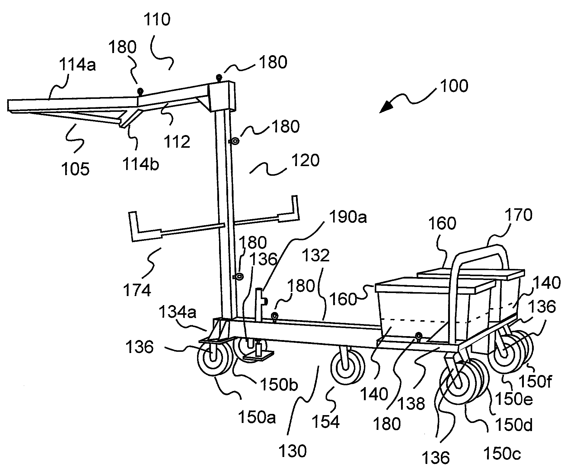
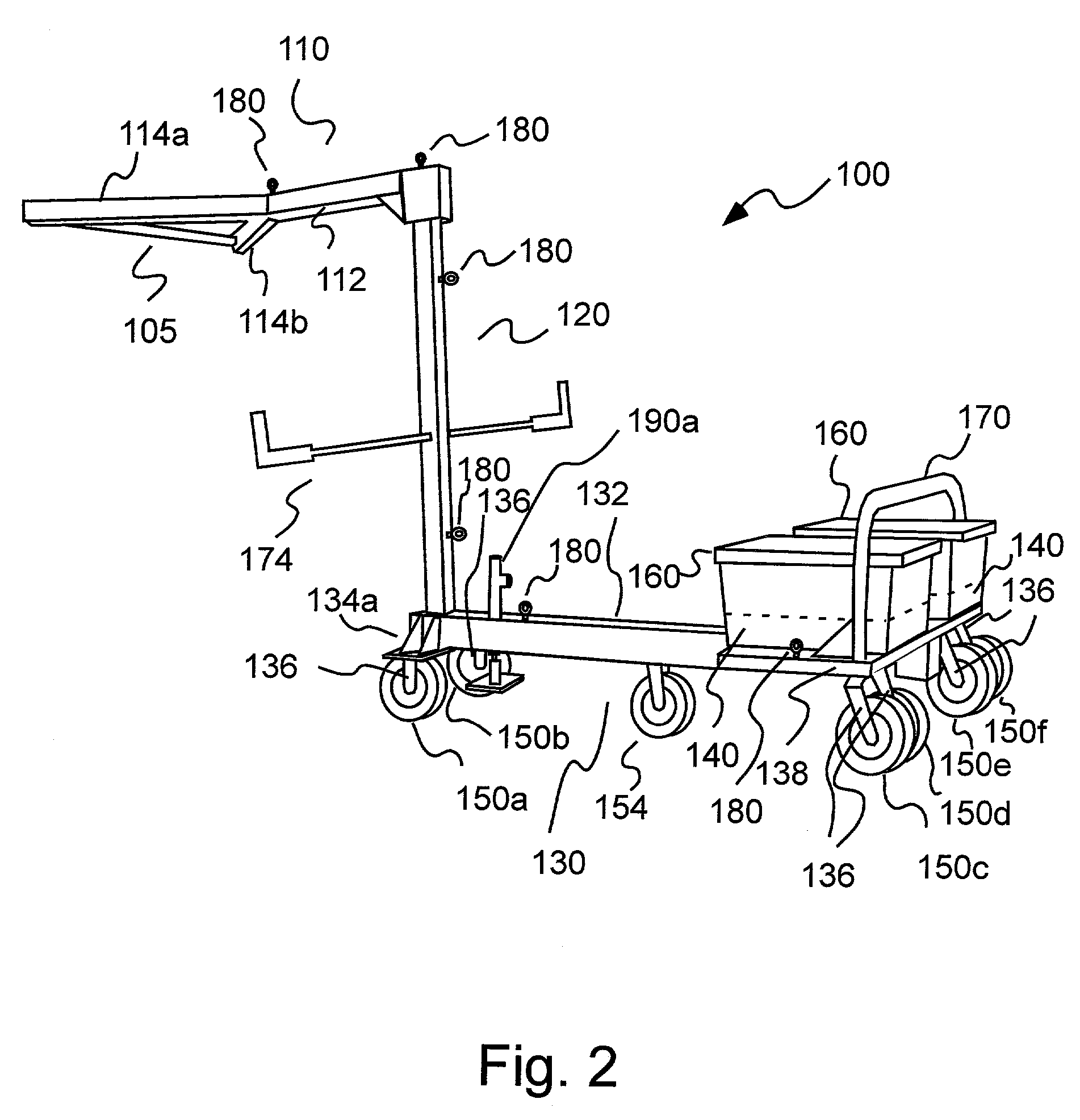
[0033]In the embodiment illustrated in FIGS. 2 through 5F, the present invention provides an overhead anchoring device or system 100 that includes an anchor member 105 attached to one end of a generally horizontally extending member 110. In the embodiment of FIGS. 2–5F, horizontal extending member 110 includes a first generally horizontal member 112 to which two extending member 114a and 114b are attached at generally opposing angles in the form of a “Y”. Anchor member 105, in this embodiment, is a transverse bar extending between the forward end of extending members 114a and 114b. Anchor member 105 can, alternatively, be attached directly to a horizontal extending member such as generally horizontal member 112 in the general form of a “T”.

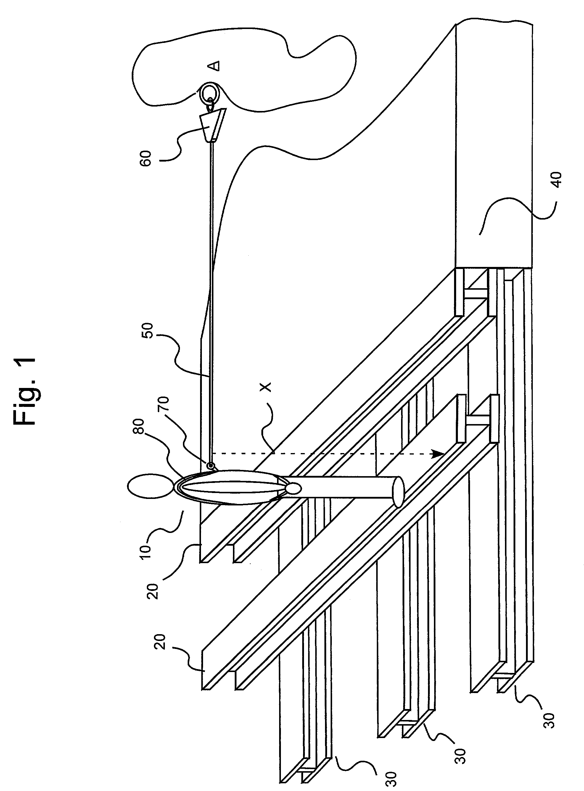
[0034]As used herein, the term “forward” refers to a direction toward the anchor member of the anchoring devices or systems of the present invention. The term “rearward”: refers to an opposite direction, away from the anchor member.

[0035]Generally...


PUM


Abstract

An anchoring system includes an anchor member to anchor the lifeline and at least one extending unit to extend the anchor member out to a working position beyond (horizontally) and above (vertically) an edge to provide for an overhead anchoring point. The anchoring system preferably further includes a support to which the extending unit is attached. The support immobilizes the overhead anchoring system so that the anchor member remains at the working position (even in the case of a fall by the worker). A method of anchoring a fall protection lifeline for use by a worker working at or beyond an edge includes the steps: elevating an anchor member to position the lifeline above the head of a worker and supporting the anchor member at the working position. The method can also include the step of extending the anchor member to a working position horizontally beyond and above the edge.

Description

BACKGROUND OF THE INVENTION[0001]The present invention relates to anchor point devices, systems and methods for use in fall protection, and, especially, to mobile, overhead anchoring devices, systems and methods for use by personnel working at an edge, for example, the leading edge of a construction project or other structure.[0002]Fall protection systems including safety harnesses and lanyards are commonly used to protect persons subjected to the potential of a fall from a height. Typically, a lifeline or lanyard is connected to an overhead anchorage point on a structure. However, in many cases (for example, leading edge work and work on the highest completed deck of a construction project), suitable overhead fall protection anchorage may not exist.[0003]For example, FIG. 1 illustrates a worker 10 positioned at the leading edge of a portion of a deck of a construction project. In general, in extending the deck in a horizontal direction, lateral I-beams 20 (for example, aluminum I-b...

Claims


Application Information

Patent Timeline
Patent Type & Authority Patents(United States)
IPC IPC(8): E04G3/28A62B1/16E04G1/36A62B1/04E04G21/32
CPCA62B35/0068E04G21/3261E04G21/3233E04G21/3238E04G21/3276
Inventor ANDERSON, PRESTON L.ADAMS, RONALD W.SPOTTS, STEVE D.GAYDOS, MICHAEL J.
Owner SPERIAN FALL PROTECTION
Why Eureka
Try Eureka