Flexible printed circuit connector

a flexible printed circuit and connector technology, applied in the direction of coupling contact members, coupling device connections, electrical devices, etc., can solve the problems of troublesome assembling the first fpc to the conventional fpc connector, insufficient force to retain the second fpc, and complicated smt procedur

Inactive Publication Date: 2006-04-25
CHENG UEI PRECISION IND CO LTD
View PDF11 Cites 24 Cited by
  • Summary
  • Abstract
  • Description
  • Claims
  • Application Information

AI Technical Summary

Benefits of technology

[0006]An object of the present invention is to provide a flexible printed circuit (FPC) connector for easy assembling flexible printed circuits thereto and reliably retaining the flexible printed circuits therein.
[0007]Another object of the present invention is to provide a FPC connector for precisely retaining a first FPC therein.
[0008]A further object of the present invention is to provide a FPC connector for precisely retaining a second FPC therein.
[0012]A pair posts is formed on the top surface of the dielectric housing extending upwardly into the second receiving space. When the second flexible printed circuit is inserted into the second receiving space, the posts come into positioning holes of the second flexible printed circuit to anchor the second flexible printed circuit, thereby reliably and precisely retaining the second flexible printed circuit in the flexible printed circuit connector.

Problems solved by technology

It is well known that the SMT procedure is complicated and the conditions for the operation of SMT are too strict, thereby creating the problem that it is troublesome to assemble the first FPC to the conventional FPC connector.
However, conventional engagement means usually cannot provide enough force to retain the second FPC.
Furthermore, the conventional connector has no anchoring mechanism to locate the second FPC, so that the second FPC can not be ensured to be precisely and reliably retained in the conventional connector, which may result in a bad electric effect.

Method used


Image

  • Flexible printed circuit connector
  • Flexible printed circuit connector
  • Flexible printed circuit connector

Examples


Embodiment Construction

[0025]Reference will now be made in greater detail to the preferred embodiment of the present invention.

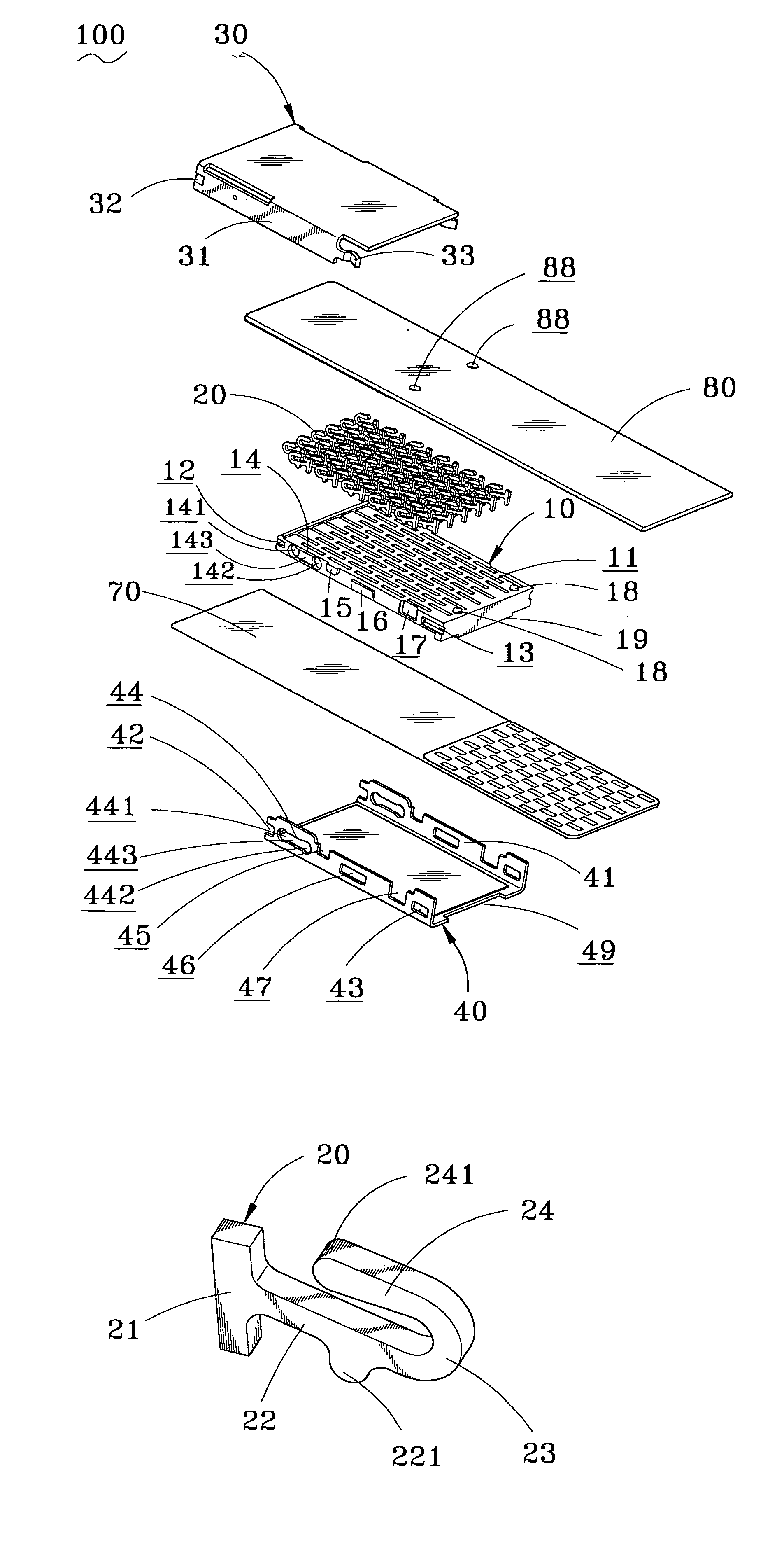
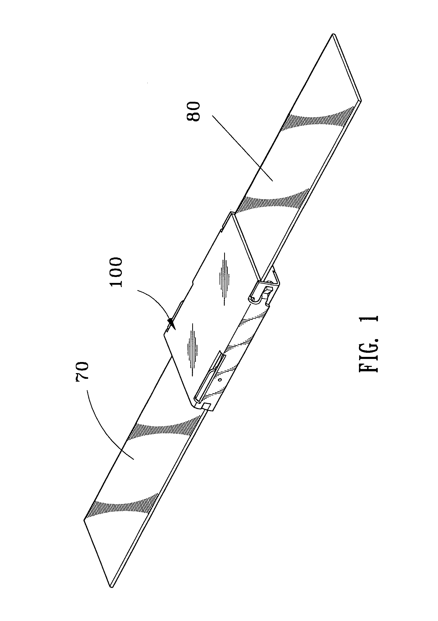
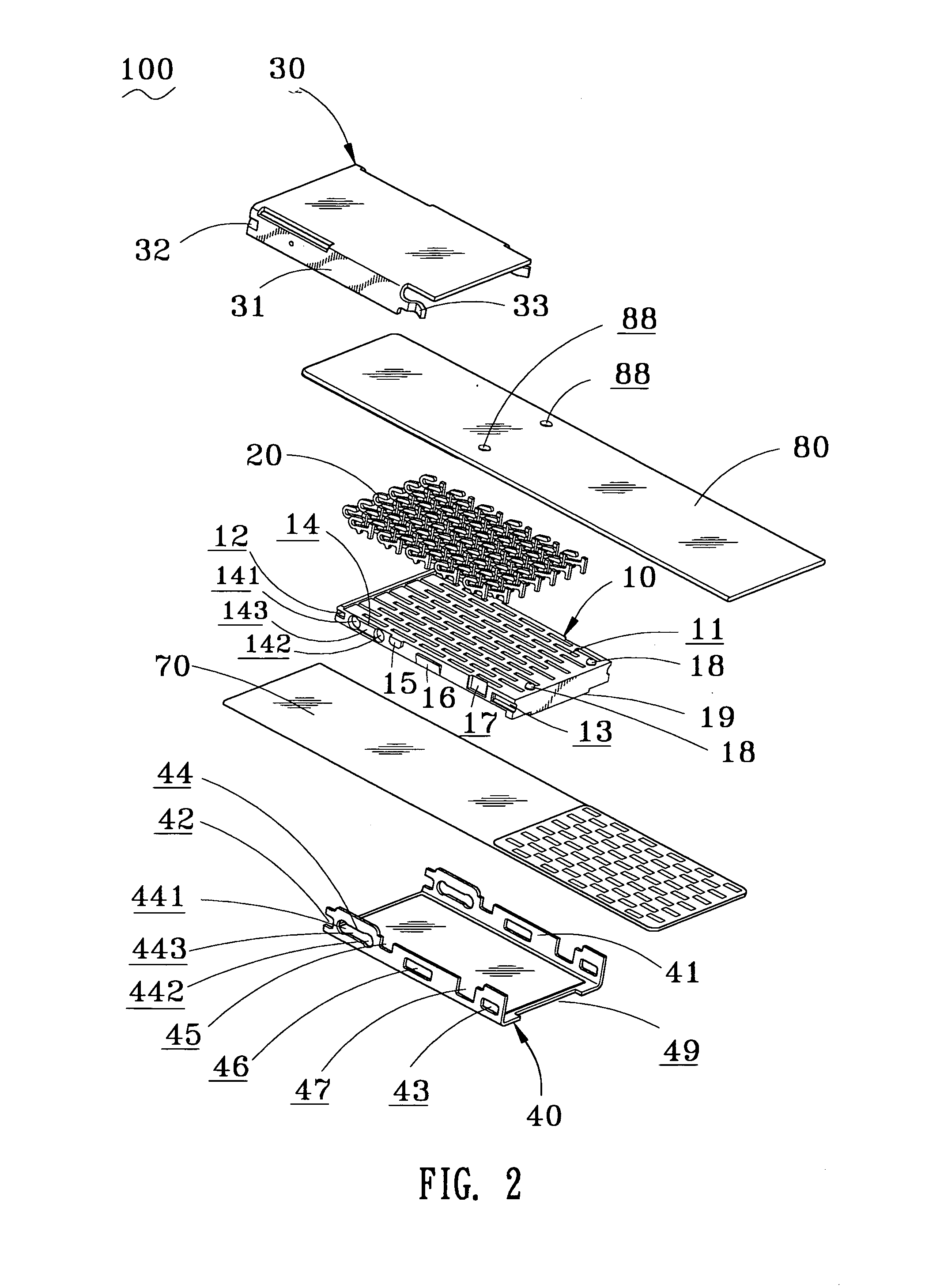
[0026]Referring to FIGS. 1 and 2, a FPC connector 100 according to the present invention comprises a dielectric housing 10, a plurality of contacts 20 contained in the dielectric housing 10, a top cover 30 and a bottom cover 40. The bottom cover 40, as shown in FIG. 6, is mounted on a bottom side of the dielectric housing 10 to define a first receiving space 50 therebetween for accommodating a first flexible printed circuit 70. The top cover 30, as shown in FIG. 7, is mounted on a top side of the dielectric housing 10 to define a second receiving space 60 therebetween for accommodating a second flexible printed circuit 80.

[0027]With reference to FIG. 2, the dielectric housing 10 has a plurality of contact chambers 11 for receiving respective contacts 20. Each contact chamber 11 extends through the dielectric housing 10 so that the contact chamber 11 is open to a top surface and a ...


PUM


Abstract

A flexible printed circuit connector includes a housing with contact chambers for receiving a plurality of contacts. The housing sets engagement recesses, first sliding grooves and protrusions on both side surfaces thereof. A bottom cover is mounted on the housing at the underside thereof to define a first receiving space for receiving a first flexible printed circuit. A top cover is mounted on the housing on the top thereof to define a second receiving space for containing a second flexible printed circuit. The top cover is engaged with the bottom cover to retain the two flexible printed circuits reliably and precisely.

Description

BACKGROUND OF THE INVENTION[0001]1. Field of the Invention[0002]The present invention relates to a connector for flexible printed circuits, especially to a flexible printed circuit connector for easy assembling flexible printed circuits thereto and retaining the flexible printed circuits reliably and precisely.[0003]2. The Related Art[0004]Flexible printed circuit (FPC) is high resilient and lightweight, so that it is widely used in electrical devices. A FPC connector is used to electrically connect a FPC to another FPC, or a rigid printed circuit, or other electrical components. One such conventional FPC connector, as shown in FIG. 11, is provided for permanent connecting a first FPC on one end thereof and provides a receiving slot on the other end thereof to receive a second FPC. The permanent connecting of the first FPC to the conventional FPC connector is performed by Surface Mounting Technology (SMT). It is well known that the SMT procedure is complicated and the conditions for...

Claims


Application Information

Patent Timeline
Patent Type & Authority Patents(United States)
IPC IPC(8): H01R12/24
CPCH01R12/774H01R12/78H01R13/24
Inventor HUANG, CHUNG HSINKAO, YI CHIUPENG, YUNG CHI
Owner CHENG UEI PRECISION IND CO LTD
Why Eureka
Try Eureka