Method and arrangement for monitoring the drive of an actuator

Inactive Publication Date: 2006-04-25
ROBERT BOSCH GMBH
View PDF9 Cites 0 Cited by
  • Summary
  • Abstract
  • Description
  • Claims
  • Application Information

AI Technical Summary

Benefits of technology

[0004]A monitoring in a simple and reliable manner is provided of the circuit arrangement lying between output stage and microcomputer by the determination of the actual switch-on

Problems solved by technology

These additional elements, especially in the case of a fault, can falsify the conversion of the drive signal quantity

Method used


Image

  • Method and arrangement for monitoring the drive of an actuator
  • Method and arrangement for monitoring the drive of an actuator
  • Method and arrangement for monitoring the drive of an actuator

Examples


Embodiment Construction

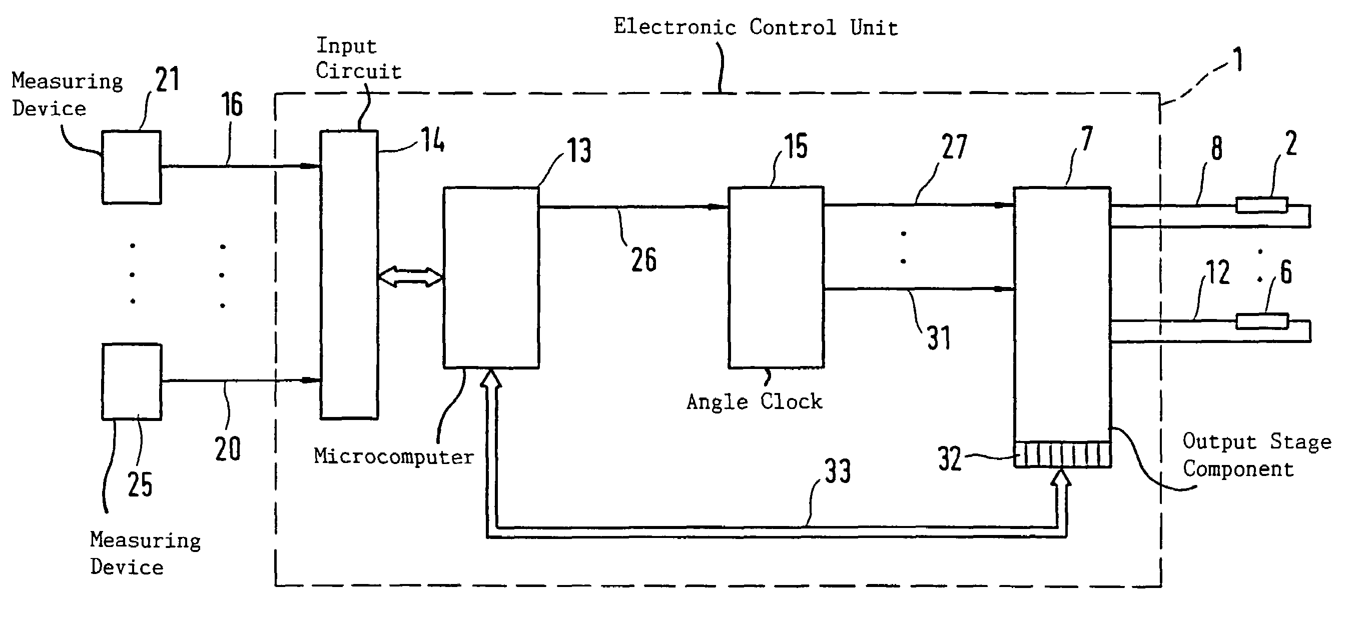
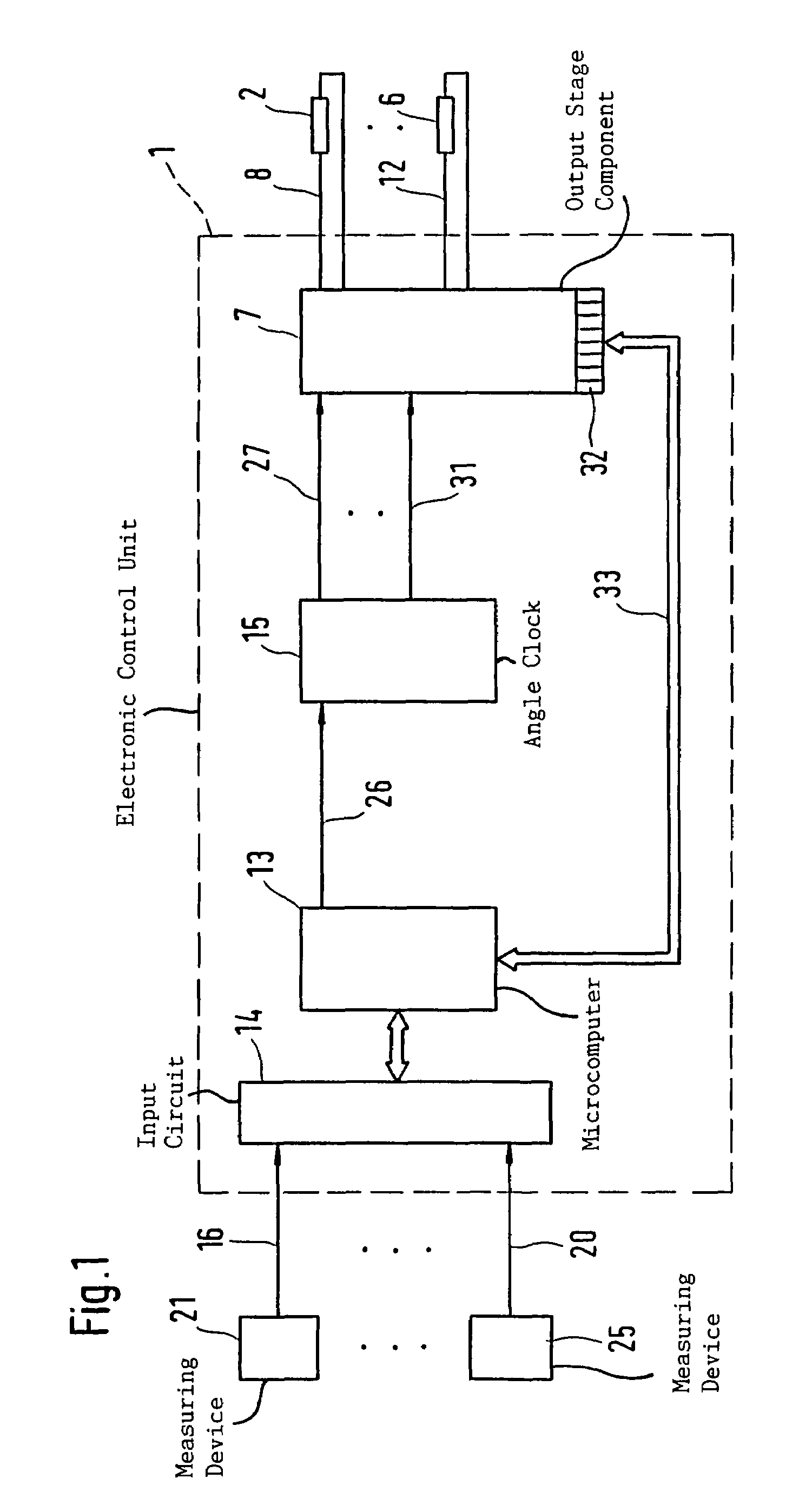
[0011]FIG. 1 shows an electronic control unit 1, which, inter alia, actuates injection valves 2 to 6 of an internal combustion engine. For this purpose, the control unit 1 includes an output component 7 to which the injection valves 2 to 6 are connected by lines 8 to 12. In addition, the electronic control unit 1 includes a microcomputer 13. The microcomputer 13 is connected at its input end to an input circuit 14, and, at its output end, to a component 15 which includes, for example, a so-called angle clock. Input lines 16 to 20 are connected to the input circuit 14 and these lines connect the control unit 1 to measuring devices 21 to 25 for detecting operating variables of the engine and / or of the vehicle such as engine temperature, engine rpm, exhaust-gas composition, supplied air mass, etc. The input quantities are processed in the input circuit 14 and are supplied to the microcomputer 13. Depending upon the program implemented in the microcomputer, the latter determines drive s...


PUM


Abstract

An arrangement for monitoring the drive of an actuator includes an output-stage component which includes a counter. With the aid of the counter, the switch-on time of the actuator is determined. The determined switch-on time is made available to the microcomputer for diagnostic purposes.

Description

BACKGROUND OF THE INVENTION[0001]In modern control systems, actuators (magnetic valves, electric motors, et cetera) are driven by means of drive signals via an output stage comprising integrated circuit loops or discrete components. The drive signals are generated by computer units. An example for driving a magnetic valve for fuel injection in internal combustion engines is disclosed in U.S. Pat. No. 5,829,412. Here, a drive signal is generated by a microcomputer. This drive signal determines the switch-on time of the magnetic valve. The drive signal is converted in a downstream component (called the angle clock) into a drive signal which is supplied to the magnetic valve output stage. The angle clock has the task to convert the drive signal, which is pregiven on a time basis or angle basis, while considering the actual crankshaft angle. The drive signal is then supplied to an output stage which undertakes the actuation of the magnetic valve by supplying current. In this way, a plur...

Claims


Application Information

Patent Timeline
IPC IPC(8): H01H71/04F02D45/00F02D41/02F02D41/14F02D41/22
CPCF02D35/027F02D41/027F02D41/1443F02D41/1479F02D2200/602F02D2011/102F02D2200/0404F02D2200/0802F02D41/187
Inventor LANGER, WINFRIEDKUDICKE, BERNDECKHARDT, JUERGENMUELLER, KLAUS
Owner ROBERT BOSCH GMBH
Why Eureka
Try Eureka