Sheet separating apparatus for a fusing unit and method for using the same

Active Publication Date: 2006-04-25
HEWLETT PACKARD DEV CO LP
View PDF5 Cites 0 Cited by
  • Summary
  • Abstract
  • Description
  • Claims
  • Application Information

AI Technical Summary

Benefits of technology

[0018]The present invention has been developed in order to solve the above problems in the prior art. Accordingly, it is an aspect of the present invention to provide a sheet separating apparatus for a fusing unit capable of preventing damage to the surface of a heating roller when the sheet separating apparatus is installed or a jammed sheet is removed. Another aspect of the invention is to provide a method of easily fabricating a shapened front end of a separating claw.
[0023]Accordingly, the sheet separating apparatus for the fusing unit according to an embodiment of the present invention is capable of preventing damage to a surface of the heating roller when the sheet separating apparatus is installed or a jammed sheet is removed. Also, the sheet separating apparatus according to an embodiment of the present invention enables easily fabricating the front end of the separating claw.

Problems solved by technology

Accordingly, there is a concern that the fused sheet may not be discharged out of the image forming apparatus by the discharging roller and instead may become jammed between the heating roller and the frame.
In that case, however, there is a problem of increased fabrication cost.

Method used


Image

  • Sheet separating apparatus for a fusing unit and method for using the same
  • Sheet separating apparatus for a fusing unit and method for using the same
  • Sheet separating apparatus for a fusing unit and method for using the same

Examples


Embodiment Construction

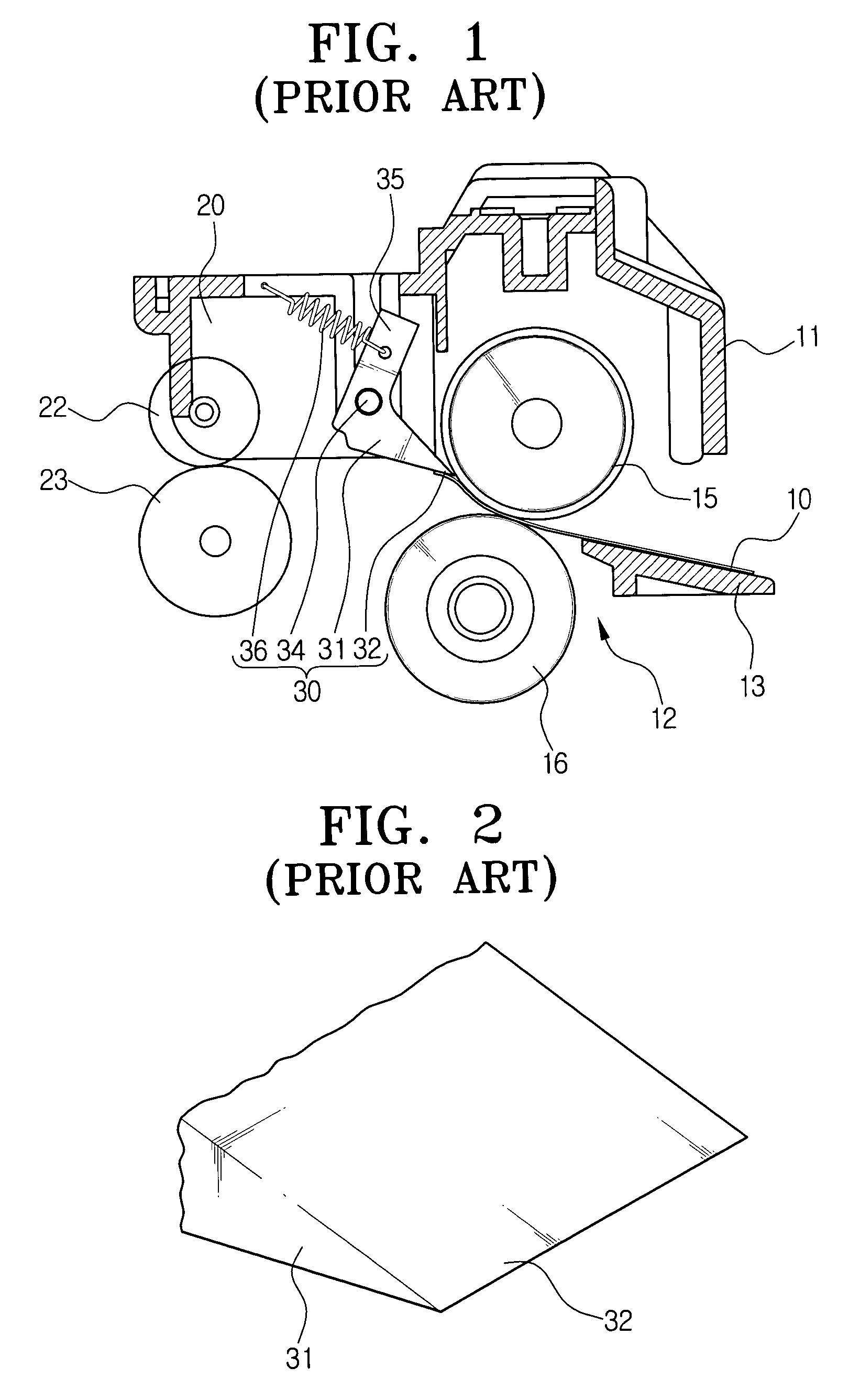
[0034]Hereinafter, an exemplary embodiment of the present invention will be described in greater detail with reference to the accompanying drawing figures. With respect to parts identical to those of the conventional apparatus discussed above, like reference numerals are assigned.

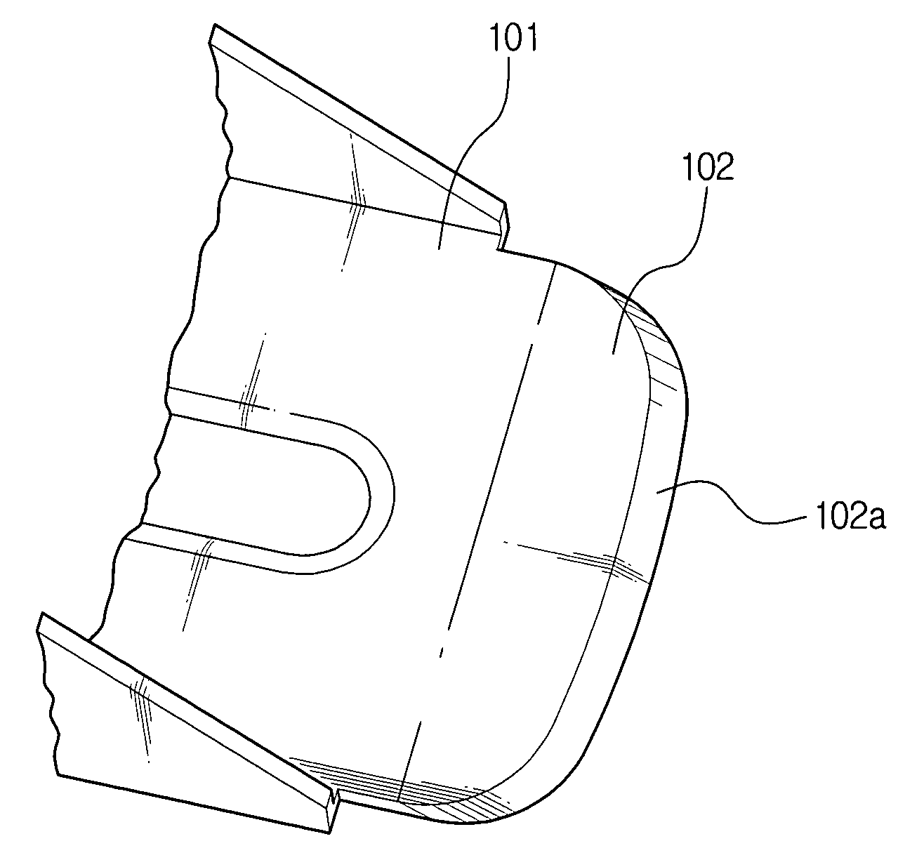
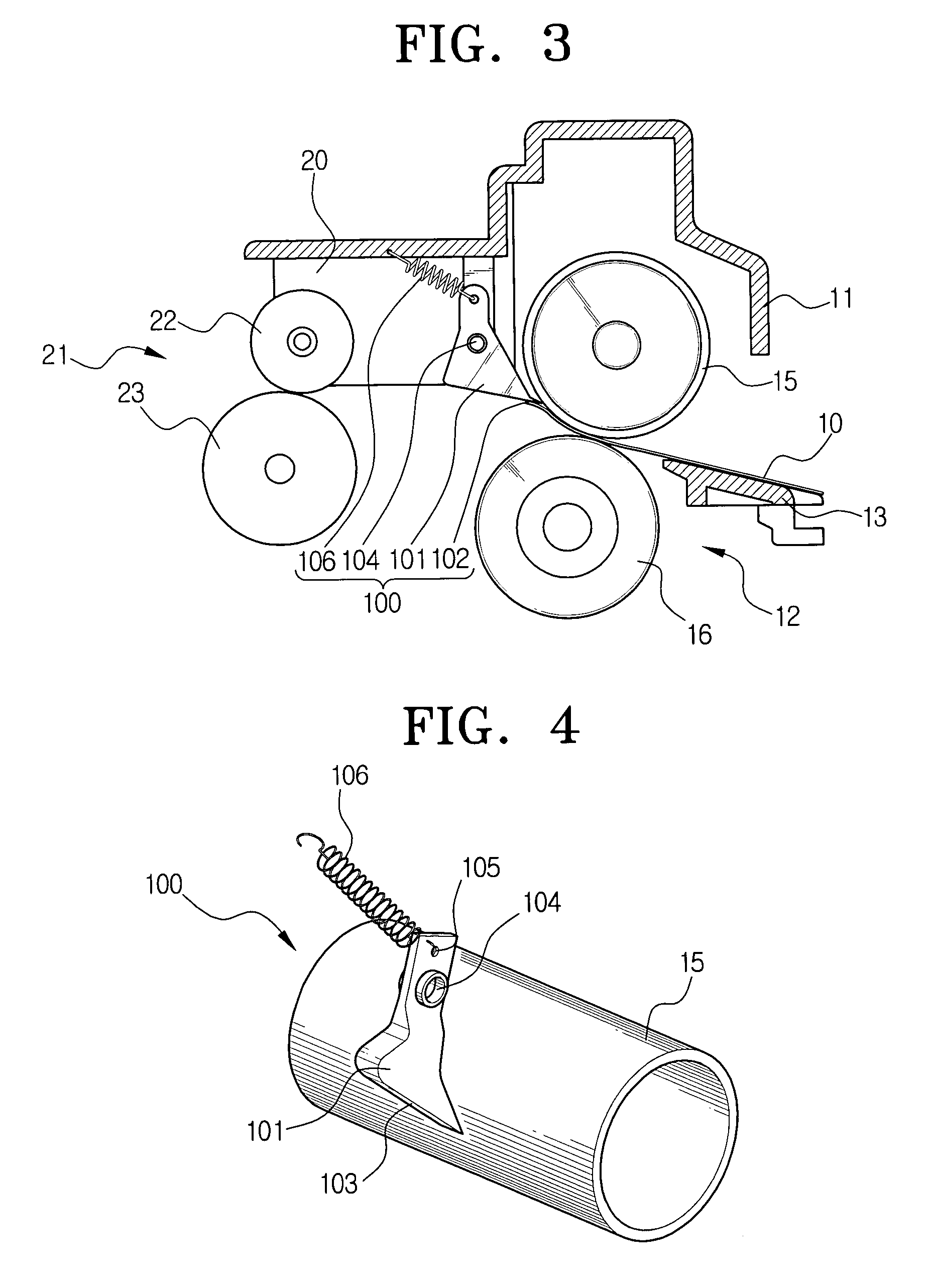
[0035]FIGS. 3 and 4 show a sheet separating apparatus 100 for a fusing unit according to an embodiment of the present invention, which includes a separating claw 101 and a contact spring 106.

[0036]The separating claw 101 is disposed toward a discharging side of a heating roller 15 to separate a sheet 10 from the heating roller 15. At this point, the separating claw 101 is pivotably assembled with a hinge 104 secured to a frame 11 and has a front end 102 constantly in contact with a surface of the heating roller 15. Also, a sheet guide surface 103 of the separating claw 101 is inclined to smoothly guide a front periphery of the sheet 10 separated by the separating claw 101 toward a sheet discharging guide 20...


PUM


Abstract

A sheet separating apparatus for a fusing unit separates a sheet being conveyed through a fusing unit from a heating roller and guides the sheet to a discharging roller without causing damages to a surface of a fusing roller. The sheet separating apparatus comprises a separating claw rotatably disposed toward a discharging side of a heating roller, for separating a sheet from the heating roller, and a contact spring pivoting the separating claw so that a front end of the separating claw is in contact with the heating roller with a predetermined constant pressure. The front end of the separating claw has rounded corners. It is preferred that the front end of the separating claw is chamfered. Also, it is preferred that the separating claw is made of stainless steel.

Description

[0001]This application claims the benefit under 35 U.S.C. §119(a) of Korean Application No. 2003-05360, filed Jan. 27, 2003, in the Korean Intellectual Property Office, the disclosure of which is incorporated herein by reference in its entirety.BACKGROUND OF THE INVENTION[0002]1. Field of the Invention[0003]The present invention relates to a fusing unit of an electrophotographic image forming apparatus, and more particularly, to a sheet separating apparatus for a fusing unit which is to separate a sheet of paper being conveyed through a fusing unit from a heating roller and guides the sheet to a discharging roller.[0004]2. Description of the Related Art[0005]An electrophotographic image forming apparatus transfers an image formed on a photosensitive medium to a sheet of printing paper and fuses the transferred image onto the sheet by using heat and pressure from a fusing unit. The fusing unit has a heating roller generating heat and a pressing roller applying pressure to the sheet, ...

Claims


Application Information

Patent Timeline
IPC IPC(8): G03G15/20
CPCG03G15/2028
Inventor LEE, BONG-HEE
Owner HEWLETT PACKARD DEV CO LP
Why Eureka
Try Eureka